Door configuration with a pivoting door and sliding door function wich can be actuated by a single actuating element

a technology of sliding door and pivoting door, which is applied in the direction of door/window fittings, wing operation mechanisms, wing accessories, etc., can solve the problems of large space required, relatively complex construction, and complicated handling, so as to facilitate the overall motion of opening the casement and improve accessibility.

Active Publication Date: 2010-05-06
BRUKER AXS
View PDF14 Cites 7 Cited by
  • Summary
  • Abstract
  • Description
  • Claims
  • Application Information

AI Technical Summary

Benefits of technology

[0036]In a further preferred embodiment, the direction V, in which the sliding door can be moved with respect to the casement, extends perpendicularly to the axis S. This has turned out to be useful in practice, in particular, in that the overall motion for opening the casement is facilitated. The axis S typically extends in a vertical direction and the direction V extends in a horizontal direction.
[0037]In another preferred embodiment, the casement has the shape of a C, wherein the open side of the C-shaped frame faces away from the axis S. This improves accessibility to the working chamber, in particular, in case of a double-wing door configuration.

Problems solved by technology

When a folding door is opened, a relatively large amount of space is required in front of the access as a pivoting area for the door.
This results in a relatively complex construction, and frequent change between the functions makes handling complicated.

Method used


Image

  • Door configuration with a pivoting door and sliding door function wich can be actuated by a single actuating element
  • Door configuration with a pivoting door and sliding door function wich can be actuated by a single actuating element
  • Door configuration with a pivoting door and sliding door function wich can be actuated by a single actuating element

Examples


Embodiment Construction

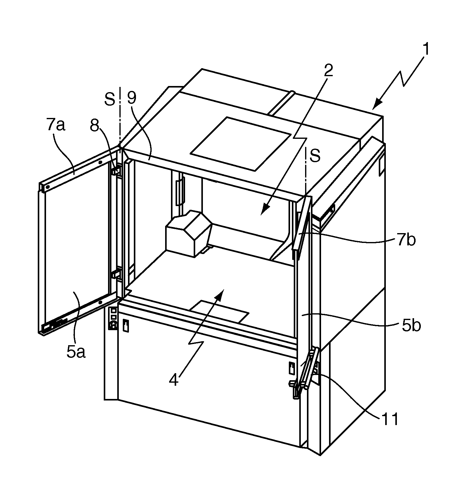
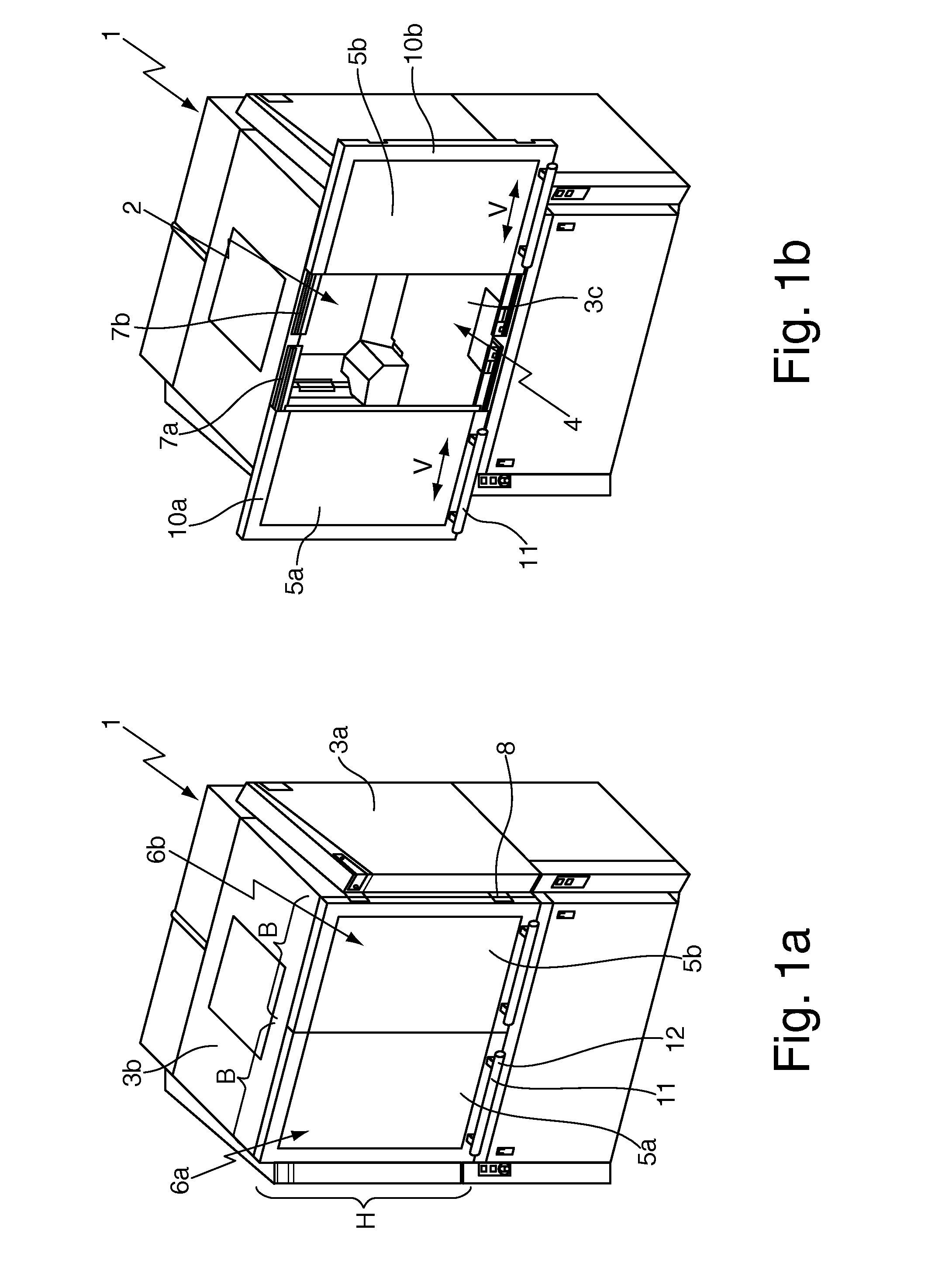
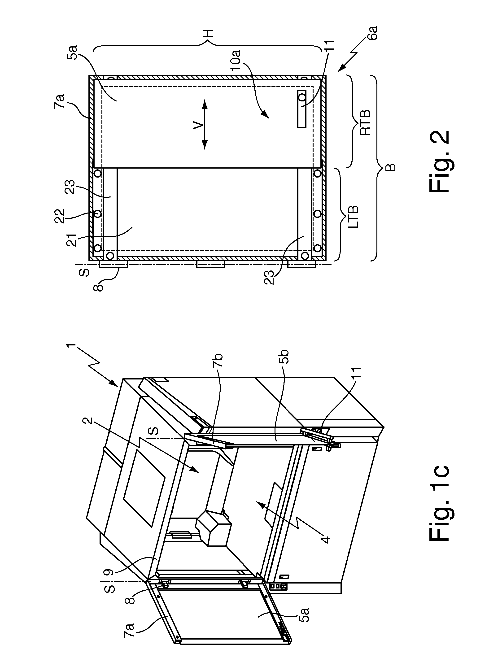
[0053]FIGS. 1a through 1c each show a cabinet-like housing, on which two inventive door configurations 1a, 1b are formed. In this example, the cabinet-like housing is designed as a safety housing 1 for an X-ray apparatus, e.g. an X-ray diffractometer or an X-ray fluorescence analysis device or a different instrumental-analytical X-ray measuring means (not shown). The safety housing 1 surrounds a working chamber 2 inside the safety housing 1, in which the X-ray apparatus can be disposed. The safety housing 1 has a plurality of stationary protection elements 3a-3c, which are impermeable to X-ray radiation, e.g. lead-containing side walls 3a, ceiling plates 3b and floor plates 3c.

[0054]The working chamber 2 has a front access 4 (FIGS. 1a-1c), which can be covered by door protection elements 5a, 5b (in the present case lead glass panes) that are impermeable to X-ray radiation. The door protection elements 5a, 5b belong to two doors 6a, 6b of the inventive door configurations 1a, 1b.

[0...


PUM


Abstract

A door configuration (1a, 1b) comprising a door (6a, 6b) for opening and closing an access (4), wherein the door (6a, 6b) can be pivoted about an axis S relative to a main frame (9) of the door configuration (1a, 1b), wherein the door (6a, 6b) has a sliding door (10a, 10b) that is disposed on a casement (7a, 7b) of the door (6a, 6b) such that it can be displaced in a direction V, and wherein the casement (7a, 7b) can be pivoted about the axis S relative to the main frame (9). A lock (32) is provided for locking and unlocking the casement (7a, 7b) in its closed state with respect to the main frame (9), and an operating element (31) is disposed on the sliding door (10a, 10b), which can be moved with the sliding door (10a, 10b) and can be switched between a first position and a second position, wherein, in the first position of the operating element (31), the operating element (31) does not obstruct movement of the sliding door (10a, 10b) on the casement (7a, 7b), and movement of the sliding door (10a, 10b) does not influence the latch position, and, in the second position of the operating element (31), the operating element (31) engages with the latch (32) or a carrier (41) that is rigidly connected or hinged to the latch (32), such that, when the casement (7a, 7b) is closed, the latch (32) is operated when the sliding door (10a, 10b) is moved in the second position of the operating element (31). The door configuration improves the operating and locking mechanism and, in particular, facilitates construction and handling.

Description

[0001]This application claims Paris Convention priority of DE 10 2008 020 729.2 filed Apr. 25, 2008 the complete disclosure of which is hereby incorporated by reference.BACKGROUND OF THE INVENTION[0002]The invention concerns a door configuration, comprising a door for opening and closing an access, wherein the door can be pivoted about an axis S relative to a main frame of the door configuration, wherein the door has a sliding door that is disposed on a casement of the door such that it can be displaced in a direction V, and wherein the casement can be pivoted about the axis S relative to the main frame.[0003]Door configurations of this type are known e.g. from doors with sliding windows (see http: / www.woelfleder.at / tuere.htm, April 2008).[0004]Door configurations are generally used to reversibly close an access, in particular, block, cover or seal it. A door configuration thereby comprises a movable part, in the present case called door, and a non-movable part, in the present case ...

Claims


Application Information

Patent Timeline
Patent Type & Authority Applications(United States)
IPC IPC(8): E05D15/58
CPCE05D15/48E05D15/581E05D2015/485E05Y2900/132
Inventor KUHNMUENCH, NORBERT
Owner BRUKER AXS
Why Eureka
Try Eureka