Prop Rod For Golf Club

a golf club and prop rod technology, applied in golf clubs, golf accessories, racket sports, etc., can solve the problems of difficult or uncomfortable retrieval of golf clubs from the ground, and achieve the effect of easy extraction and retractability

Active Publication Date: 2010-06-03
HORNE TAMMY LYNETTE
View PDF18 Cites 2 Cited by
  • Summary
  • Abstract
  • Description
  • Claims
  • Application Information

AI Technical Summary

Benefits of technology

[0005]It would thus be desirable to provide a stand assembly for a golf club that can enable the golf club to stand in an upright position when not in use. It would also be desirable for such a device to be incorporated into the club itself and to be easily extractable and retractable without affecting the functionality of the club.

Problems solved by technology

There are drawbacks to this situation particularly if the ground is wet or if the player has difficulty bending over to pick up the club or clubs on the ground.
Additionally, golfers with joint or back problems or the like may find it difficult or uncomfortable to retrieve a golf club from the ground.

Method used


Image

  • Prop Rod For Golf Club
  • Prop Rod For Golf Club
  • Prop Rod For Golf Club

Examples


Embodiment Construction

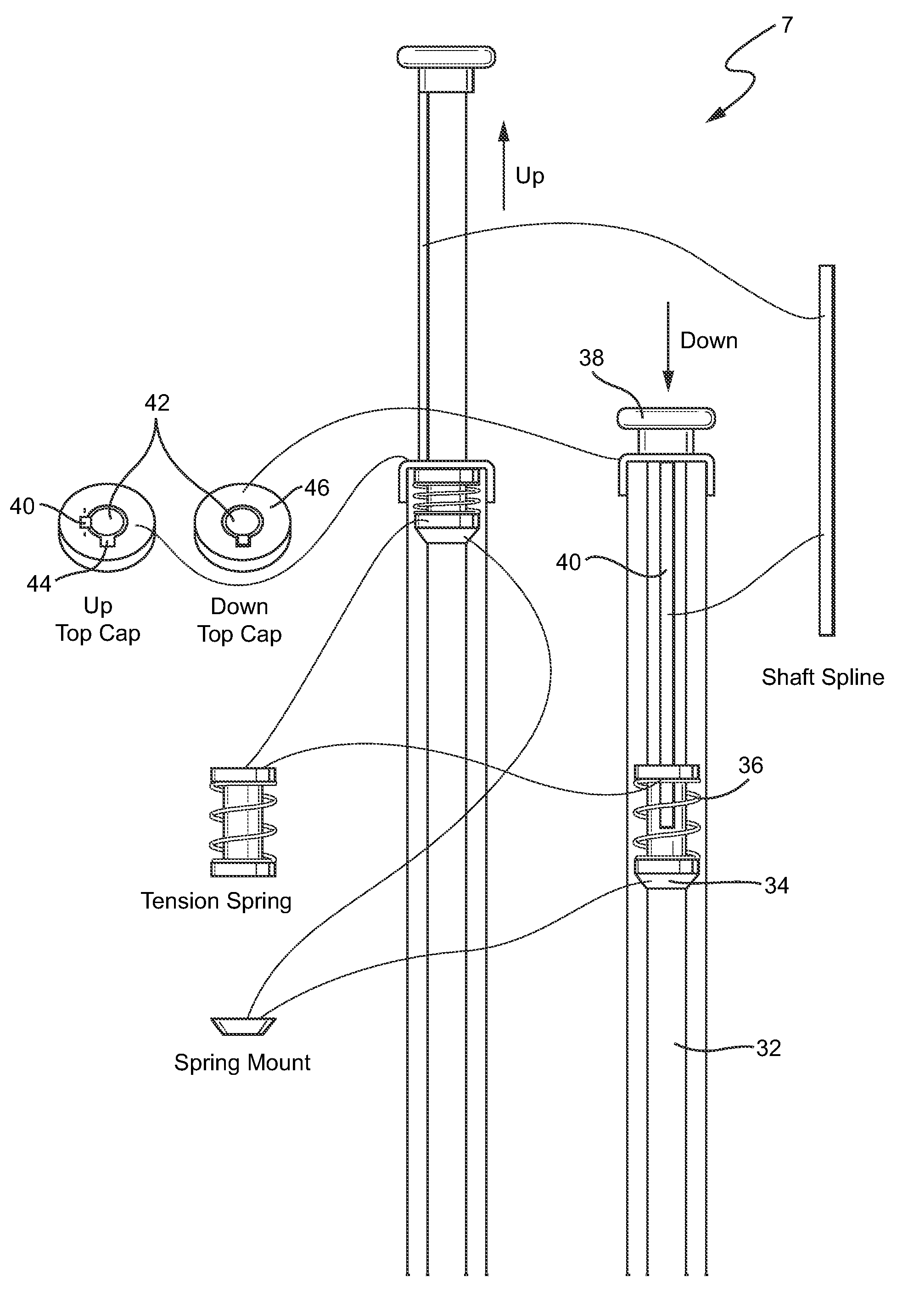
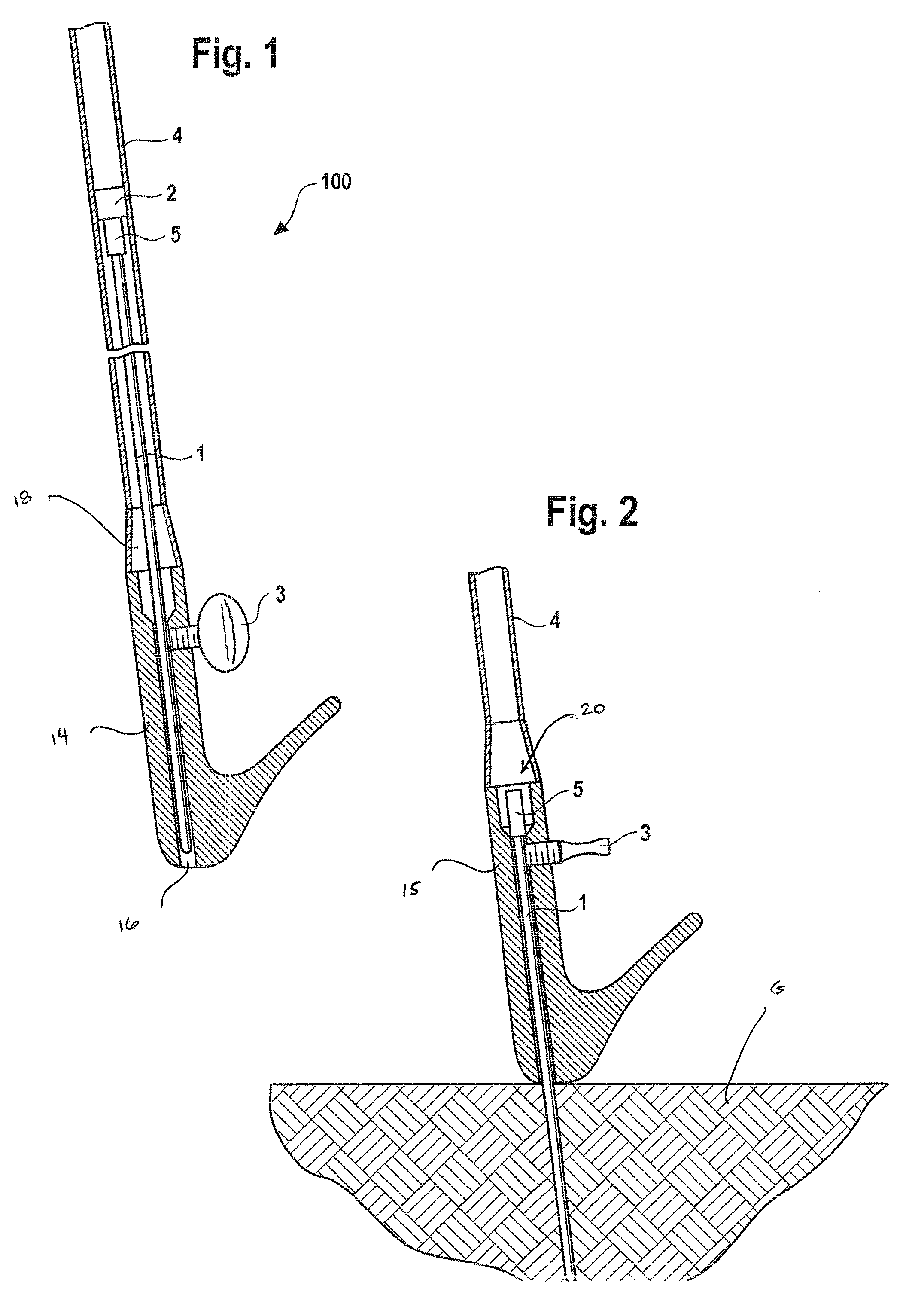
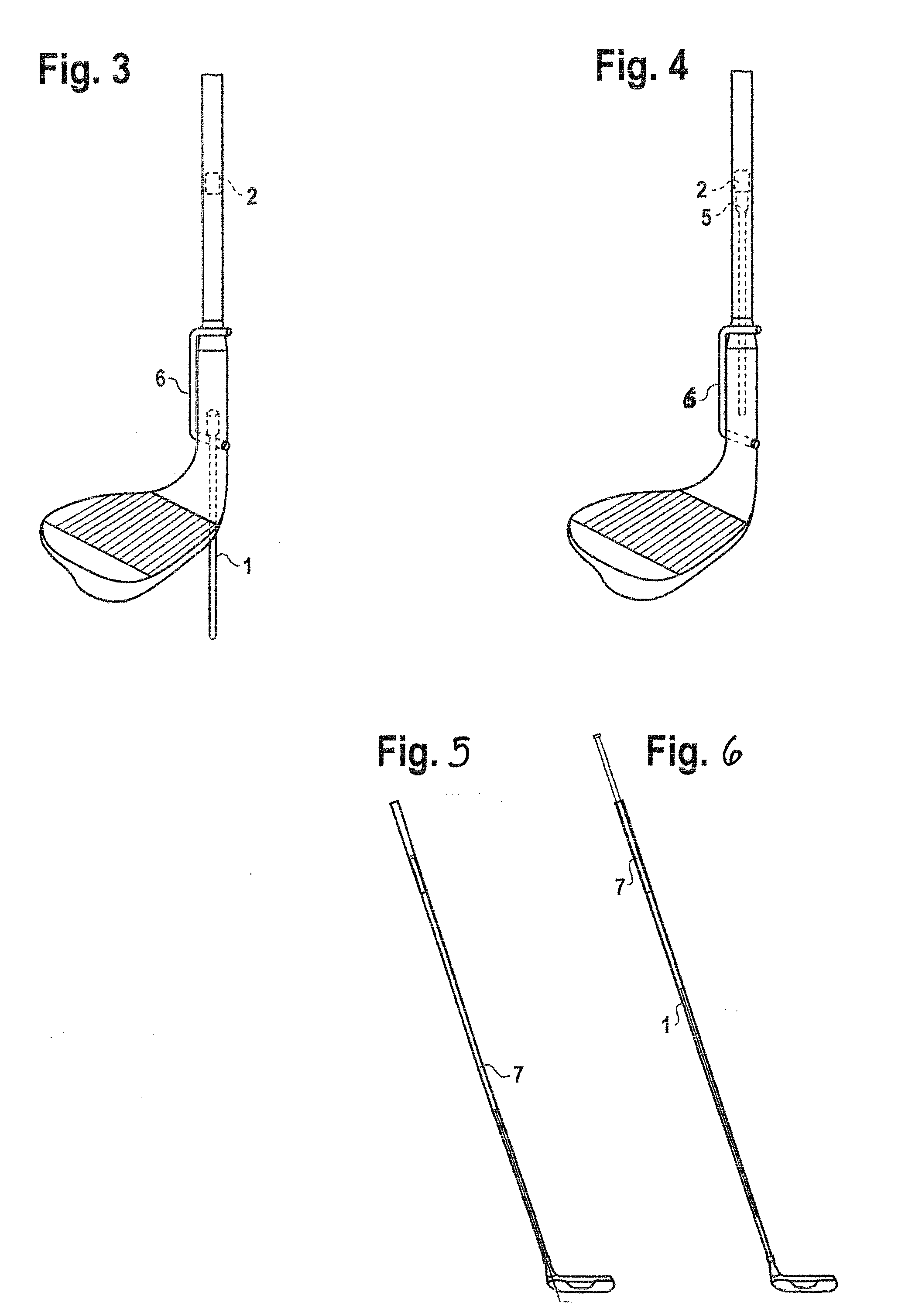
[0017]FIGS. 1 and 2 are cross sectional views of a stand assembly for a golf club according to a first embodiment. The stand assembly 100 is integrated with the golf club via a club shaft 4 and a club head 14 secured to the club shaft 4. The shaft 4 is typically hollow, and a channel 16 is formed in the club head 14, which together with the hollow club shaft define a rod channel 18.

[0018]The stand assembly 100 includes a plunge rod 1 positionable within the club shaft 4 and club head 14 and displaceable between a retracted position (FIG. 1), in which the plunge rod 1 is preferably disposed completely within the golf club, and an extended position (FIG. 2), in which at least a portion of the plunge rod 1 is extended to an exterior of the golf club. The stand assembly 100 also includes a lock 3 disposed in a position to be engageable with the plunge rod 1 in both the retracted position and the extended position. The lock 3 selectively secures the plunge rod 1 in position.

[0019]As show...


PUM


Abstract

A stand assembly for a golf club includes a plunge rod positionable within the club shaft and club head and displaceable between a retracted position and an extended position. In the extended position, at least a portion of the plunge rod is extended to an exterior of the golf club. A lock is disposed in a position to be engageable with the plunge rod in both the retracted position and the extended position. The lock selectively secures the plunge rod in at least the retracted position and the extended position.

Description

CROSS-REFERENCES TO RELATED APPLICATIONS[0001]This application claims the benefit of U.S. Provisional Patent Application Ser. No. 61 / 119,644, filed Dec. 3, 2008, the entire content of which is herein incorporated by reference.STATEMENT REGARDING FEDERALLY SPONSORED RESEARCH OR DEVELOPMENT(NOT APPLICABLE)BACKGROUND OF THE INVENTION[0002]The invention relates to a stand assembly for a golf club and, more particularly, to a retractable prop rod insertable into the ground for supporting a golf club in a standing position.[0003]When playing golf, it is not uncommon for a player to remove multiple clubs from a golf bag for executing a next stroke or series of strokes. For example, if a player's ball is close but not quite on the putting surface, the player may carry to the putting surface area a chipping club such as a wedge or the like for getting the ball on the putting surface and a putter to complete the hole after the ball is on the putting surface. For an average golfer, this is a r...

Claims


Application Information

Patent Timeline
Patent Type & Authority Applications(United States)
IPC IPC(8): A63B55/10A63B53/00
CPCA63B53/00A63B53/047A63B59/0044A63B57/00A63B55/10A63B60/28A63B60/54A63B60/0085
Inventor HORNE, PATRICK MALLORY
Owner HORNE TAMMY LYNETTE
Why Eureka
Try Eureka