Retractable rod and tent

a retractable rod and tent technology, applied in the direction of electric apparatus casings/cabinets/drawers, couplings, gaseous cathodes, etc., can solve the problems of inconvenience in reassembling and multiple steps in operation, and achieve the effect of convenient retraction

Inactive Publication Date: 2010-01-12
CHEN XIANGNIAN
View PDF9 Cites 5 Cited by
  • Summary
  • Abstract
  • Description
  • Claims
  • Application Information

AI Technical Summary

Benefits of technology

[0005]The main object of the invention is to provide rods which are easily retractable and restored in an orderly fashion.
[0009]Another embodiment is to design the tension part to have a support foot and an elastic structure linked between the ends of the ropes and the support foot. When the rope is stretched, the elastic structure is tensed, and the rod becomes rigid. When the rope is relaxed, the rope under the resilience of the elastic structure relaxes the restriction on the joints so that they can be folded up and conveniently stored.
[0016]An embodiment is to design a power input shaft to receive force; the power input shaft, through a transmission mechanism, drives the shafts of all retractable rods to rotate simultaneously. Thus, rotating the power input shaft can conveniently open or retract the tent.
[0019]Furthermore, the tent can have a control panel which is equipped with flare and remote control receiver. This make more convenient to operate the tent and use it in night.

Problems solved by technology

However, its use is still complicated by multiple steps in operation.
Particularly, when the rods are relatively long, they are easily disorganized after being folded up, causing inconvenience for reassembling.

Method used


Image

  • Retractable rod and tent
  • Retractable rod and tent
  • Retractable rod and tent

Examples


embodiment 1

of Tents

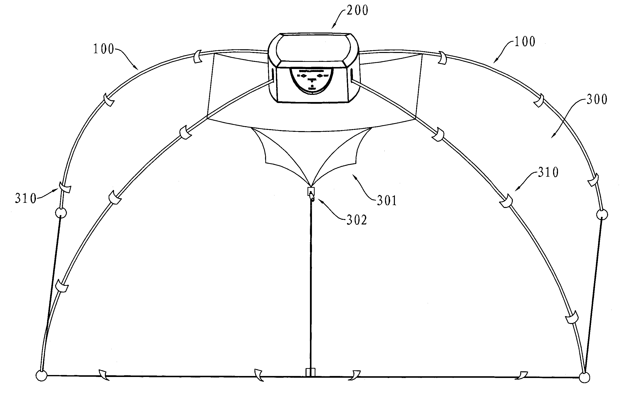
[0071]See FIG. 22, the tent of the invention is made by a rigid frame comprising three or more of the retractable rods. This embodiment uses four retractable rods 100; storage compartment is in storage box 200; tarpaulin 300 is linked by rings 310 to the rods 100. Tarpaulin is equipped with a zipper 302 to open or close door 301 to let people in or out.

[0072]See FIG. 23, after the tent is retracted as shown in FIG. 22, tarpaulin 300 is folded up inside rigid tube 141; as the tent is retracted, it takes a smaller space to store than the tents known in the art.

[0073]The following describes the structure of storage box 200. See FIG. 24, storage box 200 comprises chassis 203, covering 201, and control panel 204. The control panel is provided with a flare, a remote control receiver, and a control push-button, etc. In addition, storage box 200 has holes 202 for the four rods.

[0074]See FIG. 25, removing cover 201, one can see the top cover 205 and bottom cover 206 which are used to...

embodiment 2

of Tents

[0078]This embodiment differs from the above embodiment in the inner structure of storage box 200 which is described as follows.

[0079]See FIG. 29, removing the covers, one can see top cover 205 and bottom cover 206 which are used to support the gear system. One can also see battery 207.

[0080]See FIG. 30, removing top cover 205, one can see the gear system which include drive gear 311 which linked to the power input axis, gears 312 and 313, and worm bearing adjuster (not shown in the figure).

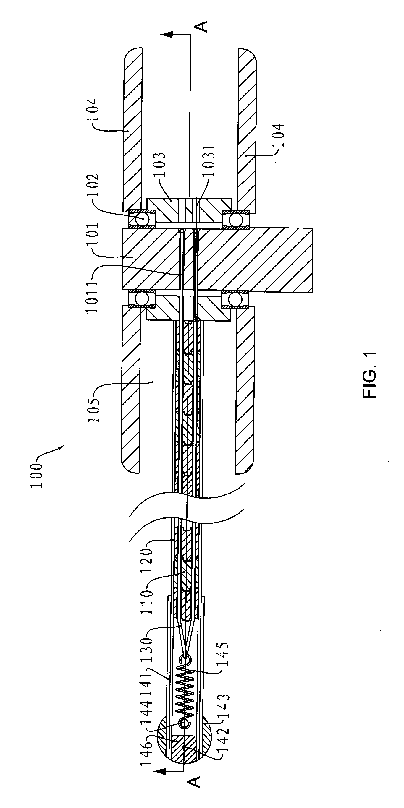
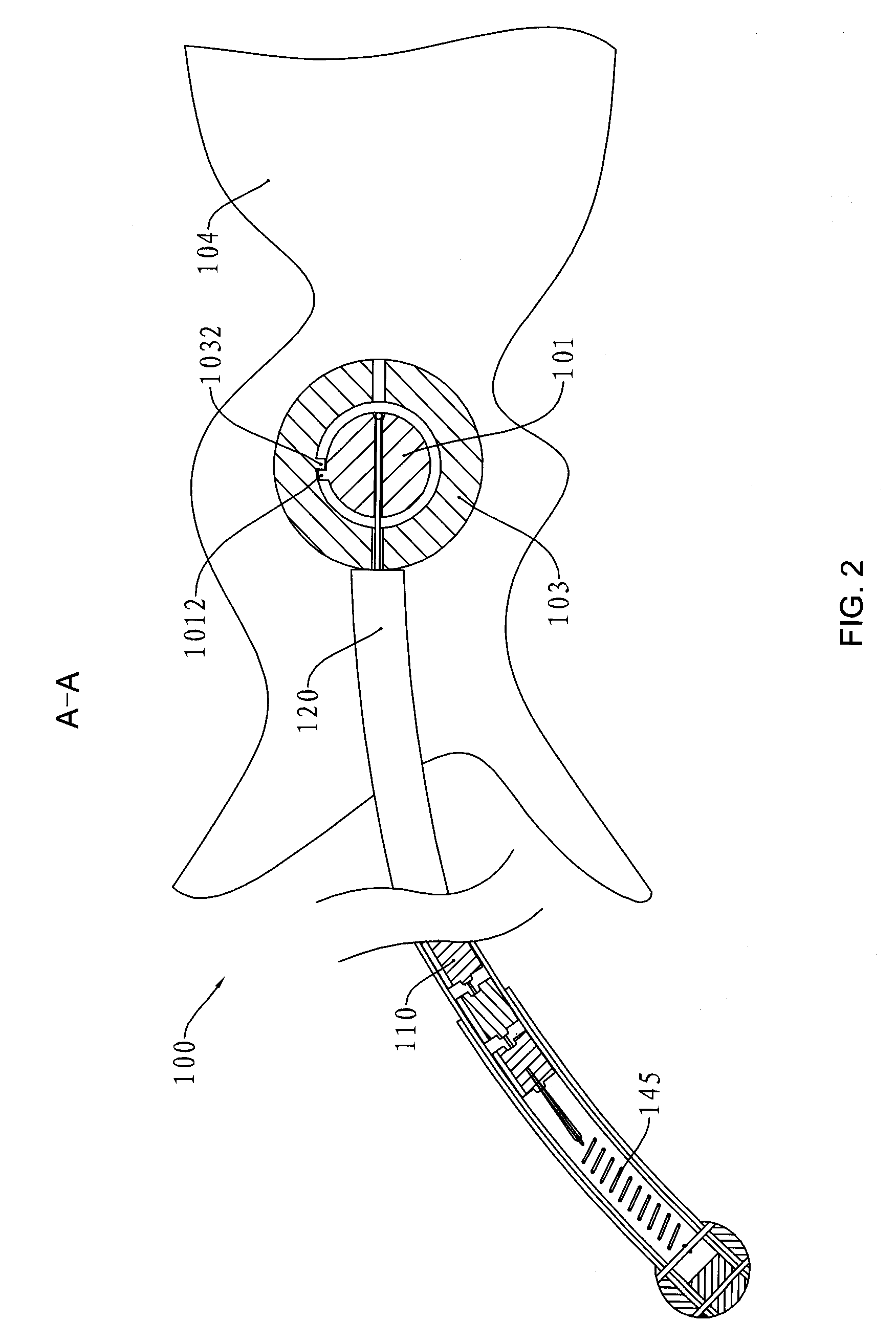
[0081]See FIG. 31, there are four retractable rods; each retractable rod has two rope-protecting boards 104. The structure of the rods is the same as the rod in embodiment 2. The rods are fixed inside storage box 200. Rod storage sleeve 103 extends to the end of rope-protecting boards 104 (see FIG. 3) which is equipped with gear 314; two gears 314 mesh with worm bearing adjuster 315. Thus, motor 320 drives the four retractable rods and rod storage sleeves 103 to rotate simultaneously. Sha...


PUM


Abstract

The invention relates to a retractable rod and a tent made from the rod. The retractable rod comprises a multitude of rigid skeleton joints having two axial end surfaces and side surfaces. The joints are connected through the convex-concave connection by two flexible ropes passing through the holes of the joints to form a rod. There is a storage compartment locating at one end of the rod which winds and stores the rod therein. The storage compartment comprises a shaft, a rod storage sleeve which is in an intermittent drive mode fixed to the shaft; one end of the two flexible ropes passes through the rod storage sleeve and is fixed to the shaft. The rod storage sleeve is supported and rotates between two rope-protecting boards. A tension part locates at the other end of the rod and the other end of the two flexible ropes is fixed to the tension part. The advantage of the invention is that the tent made from the retractable rod occupies a small storage space.

Description

CROSS REFERENCE TO RELATED APPLICATIONS[0001]This application is a Continuation-In-Part of international application PCT / CN2007 / 000238, filed Jan. 23, 2007, which claims priority from Chinese patent applications 200610033289.2 filed on Jan. 24, 2006 and 200610036648.X filed on Jul. 19, 2006. These two applications are incorporated herein by reference.[0002]The invention relates to a retractable rod and a tent made thereof.BACKGROUND OF THE INVENTION[0003]Some temporary structures such as advertising posters and tents can be taken apart and reassembled. Their frames are usually made of rods and joints. Advertising posters or tent tarpaulins are attached to the frame by gripping or other ways. Such structures occupy a reduced space after being disassembled. However, the rods require a certain length, and thus the space reduction in these structures after being disassembled is not significant.[0004]Chinese patent No. CN1027657C discloses a backbone type tent frame which consists of sev...

Claims


Application Information

Patent Timeline
Patent Type & Authority Patents(United States)
IPC IPC(8): E04H15/46E04H15/60
CPCE04H15/46Y10T403/45E04H2015/326
Inventor CHEN, XIANGNIAN
Owner CHEN XIANGNIAN
Why Eureka
Try Eureka