System for plugging a fibre optic cable into a fibre optic receptacle and cable adaptor therefor

a technology of fibre optic receptacles and systems, applied in the direction of optics, instruments, optical light guides, etc., can solve the problems of installing optical cables in situ, and achieve the effect of safe storage and negatively affecting the reliability of the connector

Active Publication Date: 2010-10-28
PRYSMIAN CABLES & SYST
View PDF6 Cites 48 Cited by
  • Summary
  • Abstract
  • Description
  • Claims
  • Application Information

AI Technical Summary

Benefits of technology

[0013]The Applicant has found that by predetermining and maintaining at a constant value the distance between an optic connector housing and the cable anchoring element of the receptacle to which the cable has to be optically and mechanically connected, and by providing a retaining element coupled with a cable adaptor—which is factory secured to the cable end and which bears a housing for an optic connector, said connector being factory coupled to the optic fibre—the cable end can be assembled in the factory, i.e. in a controlled environment, while the final mechanical and optic connections of the cable to the receptacle in the field is made easier and without need of specialized operators and tools.
[0014]Moreover, the Applicant has found that by providing a particular construction for the protective cap of the connector retaining element, the cap itself can be used as a tool for allowing a fast and precise assembly of the connector retaining element, and thus of the cable adaptor, over the cable end. Furthermore, according to the present invention, the connector retaining element in combination with the protective cap thereof advantageously ensures that the optical fibres are suitably protected during storage / transport of the pre-terminated fibre optic cable.
[0030]According to the present invention, the connector retaining element of the cable adaptor allows the pre-terminated fibre cable end to be safely stored and / or transported so that any critical movement thereof is substantially avoided. In particular, due to the flexibility of the cable, the connector retaining element avoids that the connector pivots with respect to the anchoring device, an excessive pivotal movement possibly inducing stresses on the fibres and thus adversely affecting the optical transmission thereof as well as the optic connection between the connector and the cable. Moreover, the connector retaining element according to the present invention substantially avoids any axial movement of the connector with respect to the anchoring device along the cable longitudinal axis, said axial movement modifying the distance between the connector and the anchoring device, thereby negatively influencing the reliability of the connector. Moreover, the connector retaining element according to the present invention allows that the pre-terminated fibre cable end is mechanically and environmentally protected during storage / transport of the cable. Finally, according to the present invention, the fibre optic cable can be pre-connectorizing directly in the factory so that the cable adaptor is associated to the cable in a safe and controlled environment where very skilled technical personnel as well as appropriate machinery (available for fitting, machining, polishing and testing the connector before the cable assembly is sent out for installation) can be advantageously used

Problems solved by technology

In particular, the Applicant has observed that connectorizing a fibre optic cable in situ by an installer is not advisable since said operation is time consuming and needs to be carried out in a safe and controlled environment by very skilled technical personnel.

Method used


Image

  • System for plugging a fibre optic cable into a fibre optic receptacle and cable adaptor therefor
  • System for plugging a fibre optic cable into a fibre optic receptacle and cable adaptor therefor
  • System for plugging a fibre optic cable into a fibre optic receptacle and cable adaptor therefor

Examples


Embodiment Construction

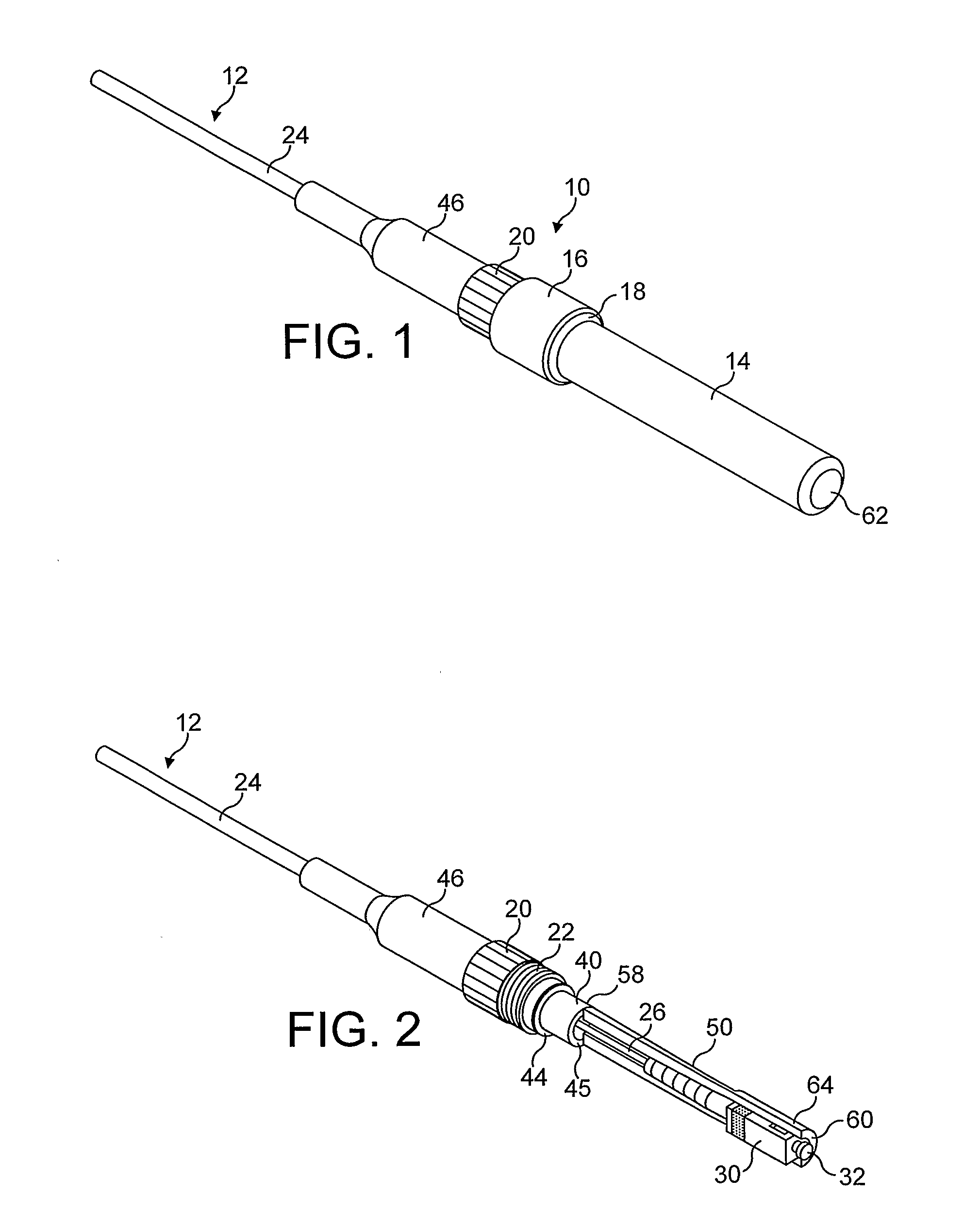
[0055]FIG. 1 shows a cable adaptor 10 according to an embodiment of the present invention. The cable adaptor 10 of FIG. 1 is represented connected to a fibre optic cable 12 which comprises an optic component 26—for transmitting an optical signal—and an outer protective sheath 24, in a radial outer position with respect to the optic component 26.

[0056]FIG. 6 shows an example of a fibre optic cable 12 to which the cable adaptor 10 of the present invention can be advantageously connected.

[0057]In detail, the cable 12 shown in FIG. 6 comprises, starting from a radial inner position thereof: one optic fibre 120, a buffer tube 121 tightly enclosing the optic fibre 120, a water swellable yarn 122, an inner sheath 123, a water swellable yarn 124, an outer sheath 125 and a protective jacket 126. According to the cable 12 of FIG. 6, the optic component 26 comprises the optic fibre 120, the buffer tube 121, the water swellable yarn 122, the inner sheath 123 and the water swellable yarn 124. Mo...


PUM


Abstract

A system for plugging a fibre optic cable into a fibre optic receptacle includes: a base element having at least one base port, and an adapter unit having at least one adapter, the at least one adapter and the at least one base port being spaced of a predetermined length. The system includes a cable adaptor associated with the fibre optic cable, the cable adaptor including a connector for being plugged into the adapter; an anchoring device for anchoring the fibre optic cable to said base port, and a connector retaining element for receiving the connector and a cable end portion, the connector retaining element defining the predetermined length and removably engaging with the anchoring device. A cable adaptor for a fibre optic cable and a method of installing a fibre optic cable into a fibre optic receptacle, especially into a joint closure, are also described.

Description

BACKGROUND OF THE INVENTION[0001]The present invention relates to a system for plugging a fibre optic cable into a fibre optic receptacle.[0002]In particular, the present invention relates to a system for plugging a fibre optic cable into a joint closure, said fibre optic cable being provided with a cable adaptor.[0003]Moreover, the present invention relates to a cable adaptor for plugging a fibre optic cable into a fibre optic receptacle, e.g. a joint closure.[0004]Furthermore, the present invention relates to a method of installing a fibre optic cable into a fibre optic receptacle.DESCRIPTION OF RELATED ART[0005]Fibre optic cables are used in an increasing number and variety of applications, such as a wide variety of telecommunications and data transmission applications. As a result, fibre optic networks include an ever increasing number of enclosures in which one or more of the optic fibres are interconnected or otherwise terminated. These enclosures also provide protection for t...

Claims


Application Information

Patent Timeline
Patent Type & Authority Applications(United States)
IPC IPC(8): G02B6/36
CPCG02B6/3849G02B6/3897G02B6/3887G02B6/4471G02B6/3889
Inventor GRIFFITHS, IANHUBBARD, PAUL
Owner PRYSMIAN CABLES & SYST
Why Eureka
Try Eureka