Indicating instrument

a technology of indicating instruments and indicating points, which is applied in the direction of instruments, indication apparatus, transportation and packaging, etc., can solve the problems of increasing the manufacture cost of variable display elements and the inability to cheaply manufacture dials, so as to improve the indication accuracy of pointers and reduce the magnetic influence of magnets

Inactive Publication Date: 2010-11-18
NIPPON SEIKI CO LTD
View PDF21 Cites 4 Cited by
  • Summary
  • Abstract
  • Description
  • Claims
  • Application Information

AI Technical Summary

Benefits of technology

[0015]The present invention relates to an indicating instrument in which a pointer is secured to a pointer drive means by att...

Problems solved by technology

Such a configuration, however, requires a punching step of forming a through hole for passing the rotation shaft through in the dial to complicate the manufacture of the dial, thereby presenting the problem of the inability to manufacture the dial inexpensively.
Especially, when a variab...

Method used


Image

  • Indicating instrument
  • Indicating instrument
  • Indicating instrument

Examples


Embodiment Construction

[0038]In the following, an embodiment in which the present invention is applied to a vehicle combination meter will be described with reference to the accompanying drawings.

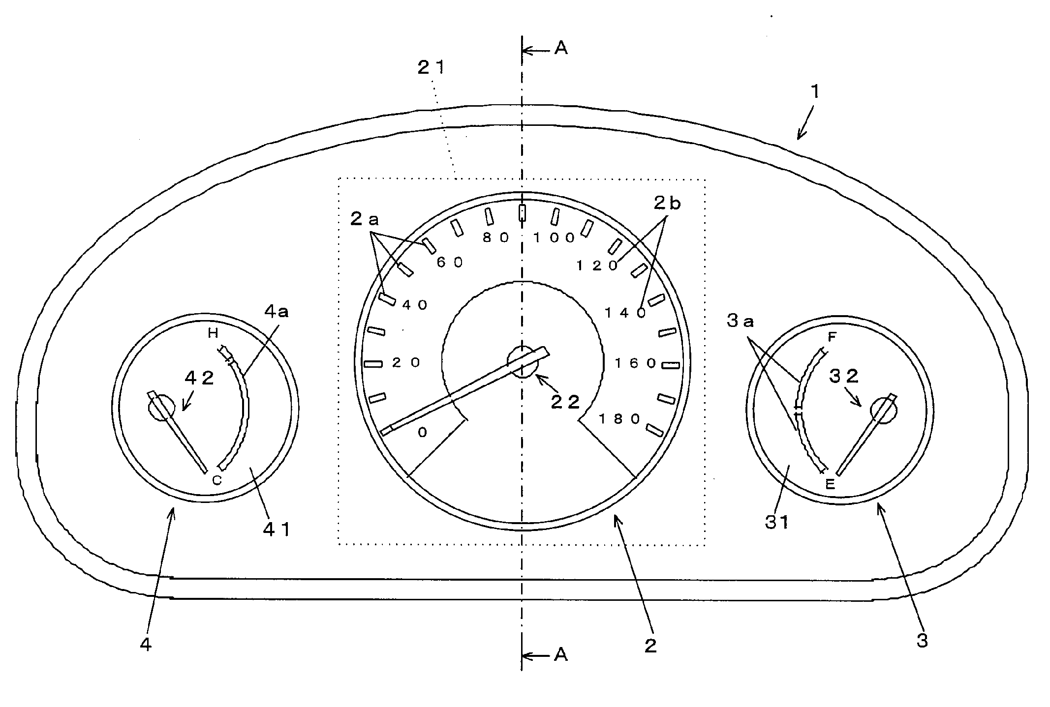
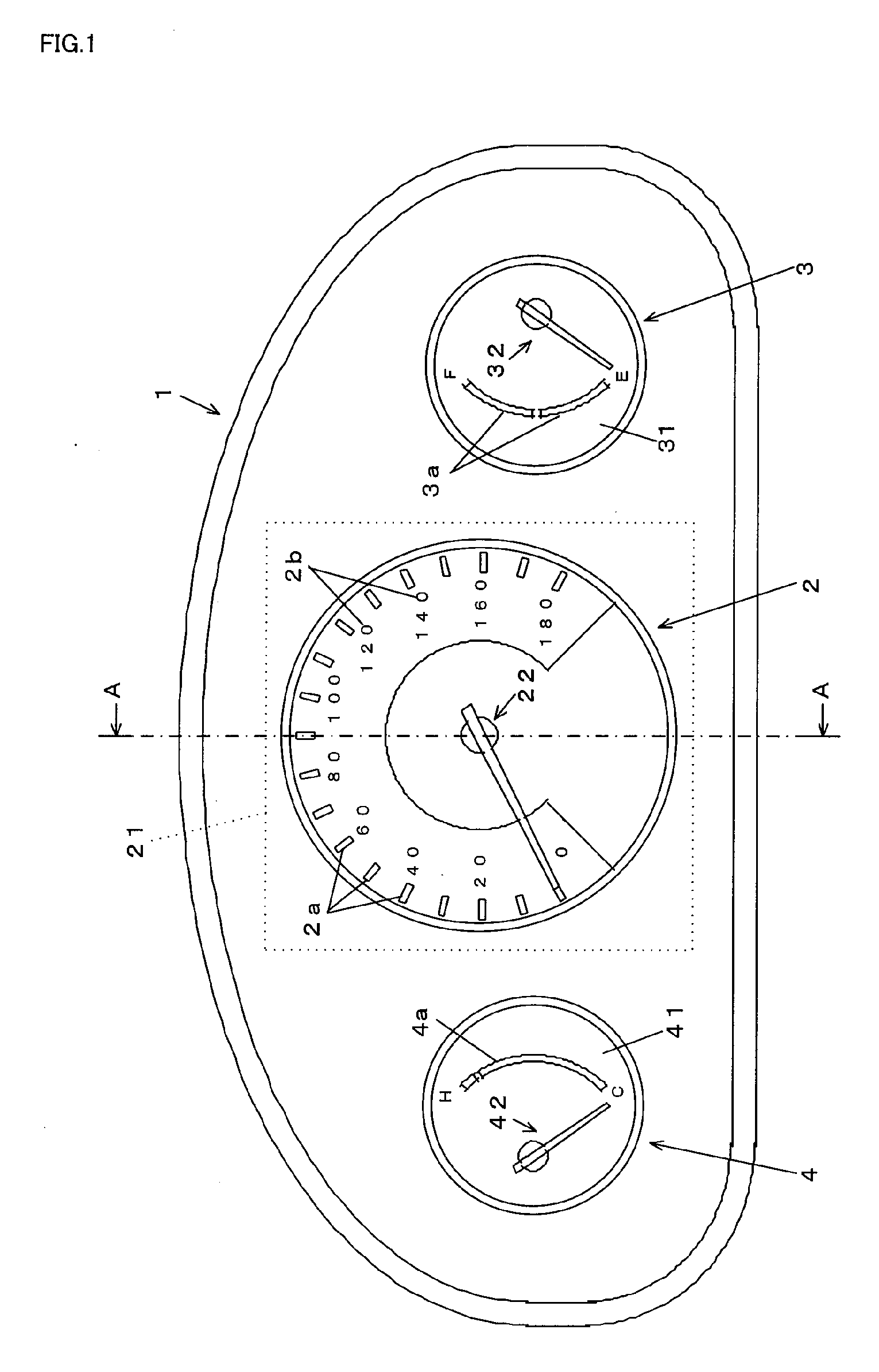
[0039]In FIG. 1, reference numeral 1 shows a housing. The housing 1 has a shade member and a case body to accommodate three indicators, that is, a speed meter 2, a fuel meter 3, and a water-temperature meter 4. The speed meter 2 is larger than the fuel meter 3 and the water-temperature meter 4 and is placed between the fuel meter 3 and the water-temperature meter 4. The speed meter 2 has a display plate 21 and a pointer 22. The fuel meter 3 and the water-temperature meter 4 have dials 31, 41, and pointers 32, 42, respectively. The dials 31, 41 are provided by forming light-shield portions through printing on substrates made of light-transmitting resin (for example, polycarbonate) except for indicating portions 3a, 4a, respectively. The pointers 32, 42 are rotated by a stepping motor (not shown) to point at the in...


PUM


Abstract

An indicating instrument is provided in which a pointer is secured to pointer drive means by attraction force of magnets and the magnetic influence of the magnets can be reduced to improve the indication accuracy of the pointer. The indicating instrument has a display plate 21, a pointer 22 provided on the front-face side of the display plate 21, and pointer drive means provided on the back-face side of the display plate 21 for rotating the pointer 22. The indicating instrument includes a first magnet 22c of ring shape provided in the pointer 22, a second magnet 23a provided in the pointer drive means such that the second magnet 23a is opposite to the first magnet 22c, a rotation drive member 24 included in the pointer drive means and rotating the second magnet 23a, and a magnetic shield member 29 provided between the second magnet 23a and the rotation drive member 24, wherein the pointer 22 is rotated in association with rotation drive of the pointer drive means by attraction force of the first and second magnets 22c, 23a.

Description

RELATED APPLICATIONS[0001]This application is the U.S. National Phase under 35 U.S.C. §371 of International Application No. PCT / JP2008 / 072799, filed on Dec. 16, 2008, which in turn claims the benefit of Japanese Application No. 2008-002947, filed on Jan. 10, 2008, the disclosures of which Applications are incorporated by reference herein.TECHNICAL FIELD[0002]The present invention relates to an indicating instrument in which a pointer points at an indicating portion on a display plate.BACKGROUND ART[0003]There have been conventionally indicating instruments in which a pointer points at an indicating portion on a dial (display plate). In such an indicating instrument, the pointer is directly secured to a rotation shaft of pointer drive means including a stepping motor or the like (rotation drive member), and the pointer is rotated in association with rotation drive of the pointer drive means and thus caused to point at the indicating portion.[0004]Such a configuration, however, requir...

Claims


Application Information

Patent Timeline
IPC IPC(8): G01D13/22
CPCB60K37/02G01D5/06B60K2350/203B60K2350/1064B60K2370/154B60K2370/33G01D2213/10
Inventor MASUDA, HIDEKI
Owner NIPPON SEIKI CO LTD
Why Eureka
Try Eureka