

Communication device and control method therefor
- Summary
- Abstract
- Description
- Claims
- Application Information
AI Technical Summary
Benefits of technology
Problems solved by technology
Method used
Image

Examples
first embodiment
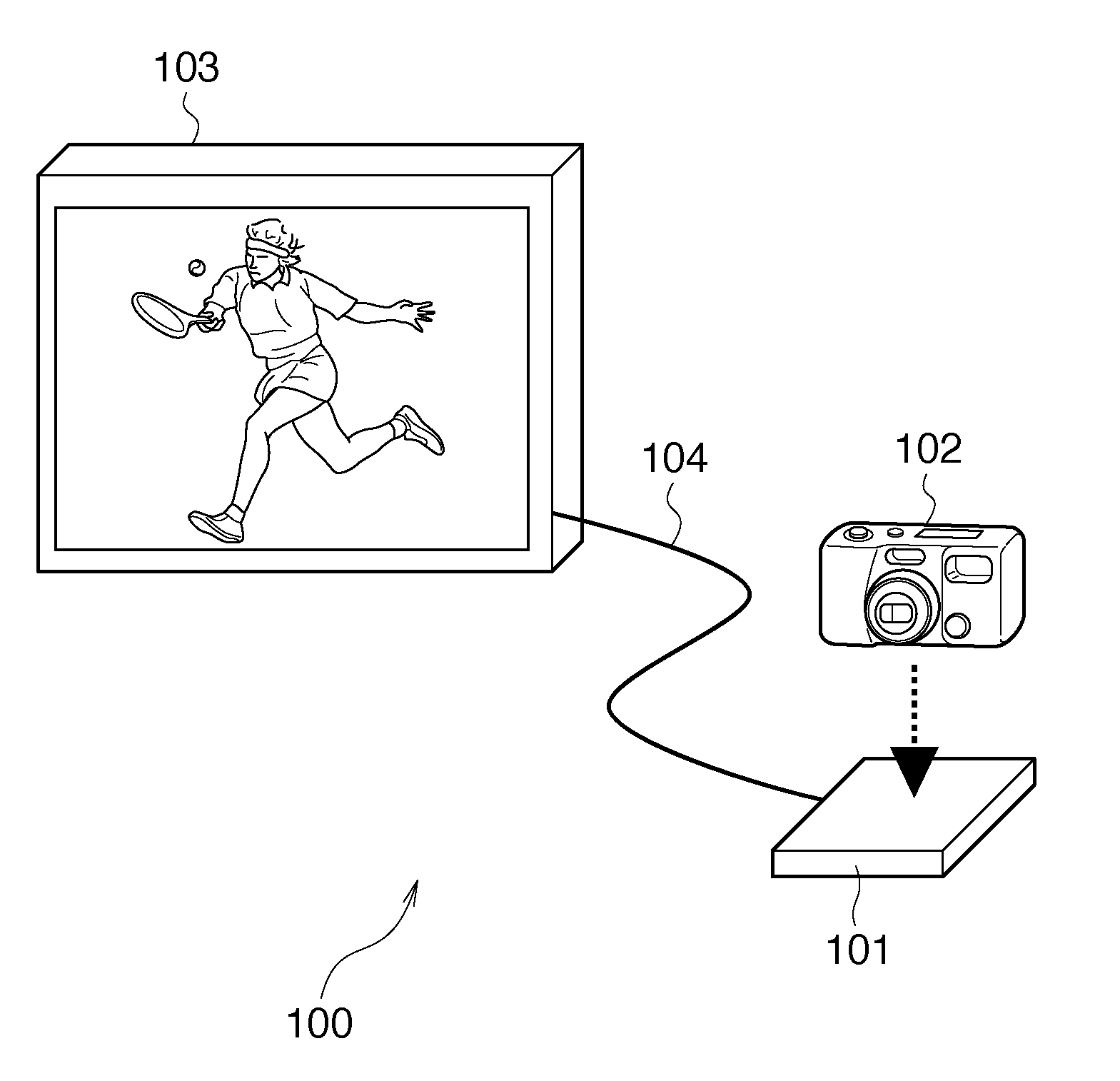
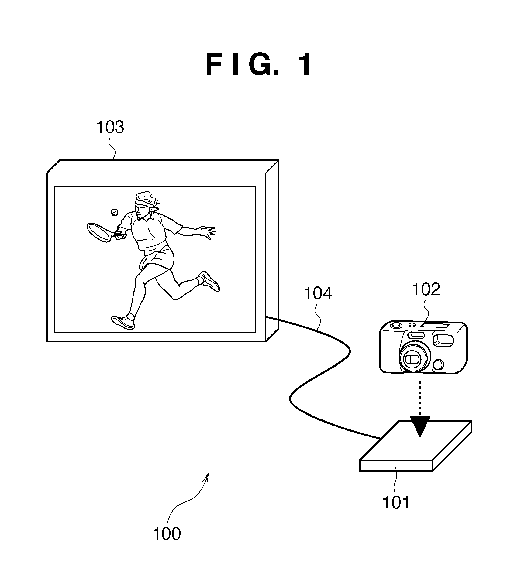
[0025]FIG. 1 is a view showing an example of a communication system including communication devices according to the first embodiment of the present invention.
[0026]Referring to FIG. 1, reference numeral 101 denotes a port device (communication device). The port device 101 includes an NFC communication means using the NFC technique, which serves as an information transmission means for executing close proximity wireless transfer using electromagnetic coupling. The port device 101 also includes a charging power supply unit serving as a non-contact power transmission means.
[0027]Reference numeral 102 denotes a mobile device (communication device) such as a digital camera. Similar to the port device 101, the mobile device 102 includes an NFC communication means. The mobile device 102 also includes a charging power receiving unit serving as a non-contact power transmission means.
[0028]Reference numeral 103 denotes a display, which is communicably connected with the port device 101 via a...
second embodiment
[0075]In the above-described first embodiment, each of the port device and the mobile device has the charging induction coil unit and wireless communication induction coil unit, separately. The present invention, however, is not limited to this.
[0076]Since the NFC communication means and the power transmission means are controlled to exclusively operate, an induction coil unit may serve as both the charging induction coil unit and the wireless communication induction coil unit, and may be switched to operate as the NFC communication means or power transmission means. The details of this embodiment will be explained below.
[0077]FIG. 7 is a block diagram showing the functional components of a port device 101 and mobile device 102 according to this embodiment. Note that different points from the functional components (FIG. 2) of the port device 101 and mobile device 102 which have been described in the above first embodiment will be explained.
[0078]The port device 101 according to this...
third embodiment
[0088]In the second embodiment, each of the port device 101 and the mobile device 102 has one induction coil unit which serves as both the charging induction coil unit and the wireless communication induction coil unit. The present invention, however, is not limited to this.
[0089]For example, an induction coil unit may serve as both a charging induction coil unit and a wireless communication induction coil unit in a mobile device 102, and a charging induction coil unit and a wireless communication induction coil unit may be separately provided in a port device 101.
[0090]Alternatively, an induction coil unit may serve as both the charging induction coil unit and the wireless communication induction coil unit in the port device 101, and the charging induction coil unit and the wireless communication induction coil unit may be separately provided in the mobile device 102.
[0091]FIG. 10 is a block diagram showing functional components when an induction coil unit serves as both the chargi...
PUM
 Abstract
Description
Claims
Application Information