Image communication apparatus and image forming apparatus including the image communication apparatus

a technology of image communication and communication apparatus, which is applied in the direction of digital output to print units, instruments, data switching networks, etc., can solve the problem of inability to check any input omission of multicast destinations, and achieve the effect of preventing the omission of necessary destinations

Active Publication Date: 2011-01-06
SHARP KK
View PDF7 Cites 21 Cited by
  • Summary
  • Abstract
  • Description
  • Claims
  • Application Information

AI Technical Summary

Benefits of technology

[0025]By the image communication apparatus and the image forming apparatus including the communication apparatus, when the user designates destinations of multicast transmission, useful information allowing the user to designat...

Problems solved by technology

In the communication apparatus disclosed in '706 Reference, however, checking of any input o...

Method used


Image

  • Image communication apparatus and image forming apparatus including the image communication apparatus
  • Image communication apparatus and image forming apparatus including the image communication apparatus
  • Image communication apparatus and image forming apparatus including the image communication apparatus

Examples


first embodiment

Overall System Configuration

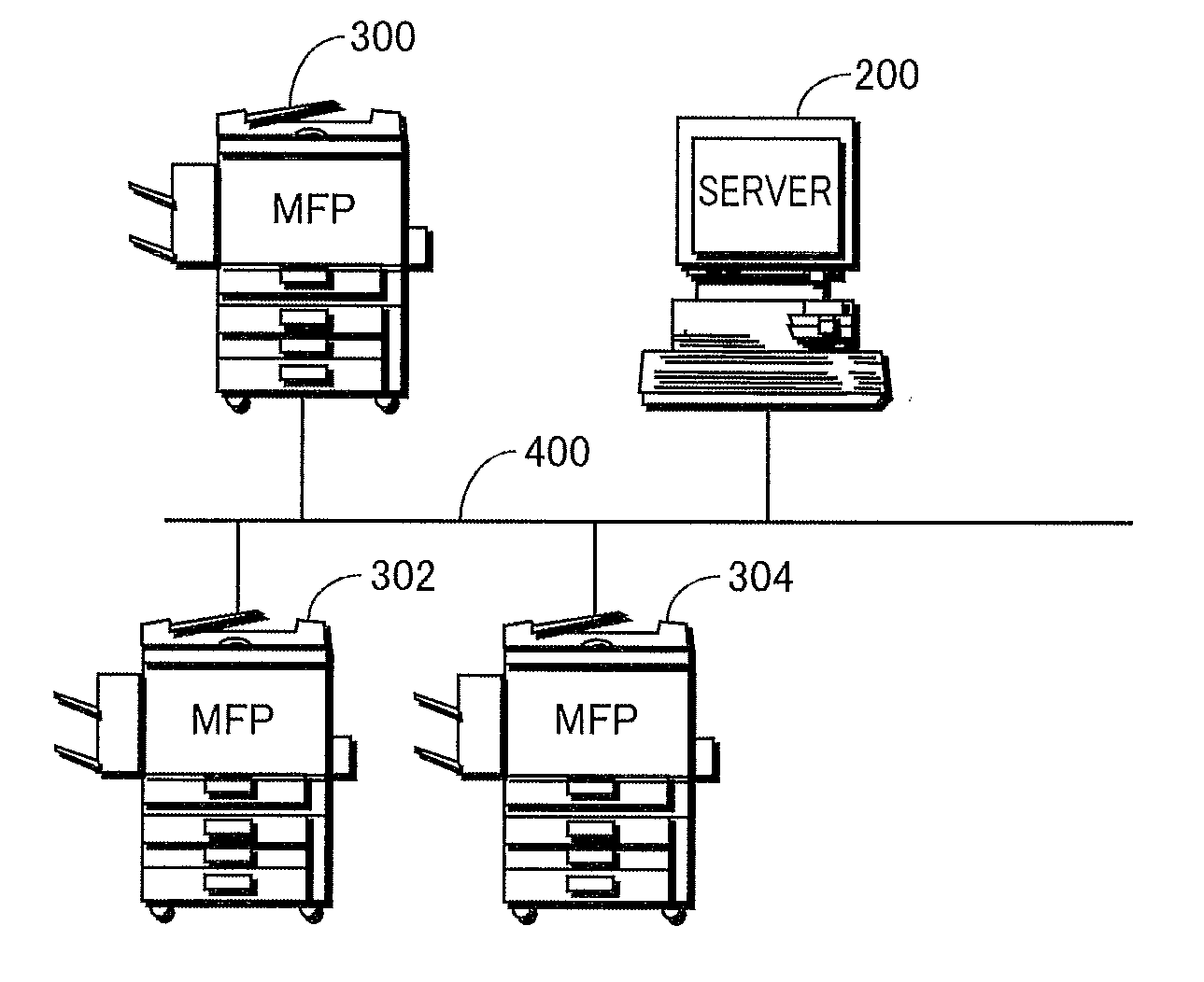
[0042]Referring to FIG. 1, an overall configuration of a network image forming system in accordance with the first embodiment of the present invention will be described. The network image forming system includes MFPs 300 to 304 multicasting image data upon reception of a multicast transmission request, and a server computer 200 receiving multicast transmission history records of users of MFPs 300 to 304 received from MFPs 300 to 304 and managing the history records. Server computer 200 and MFPs 300 to 304 are connected to be communicable with each other through a network line 400 in compliance with, for example, IEEE 802.3. It is noted that MFPs 300 to 304 do not necessarily have the same functions. In the following, description will be given with reference to MFP 300 as a representative of MFPs 300 to 304. It is naturally understood that the server computer executes the same process for each of the plurality of MFPs.

[0043]In the present embodiment, when ...

second embodiment

[0141]In the following, a second embodiment of the present invention will be described.

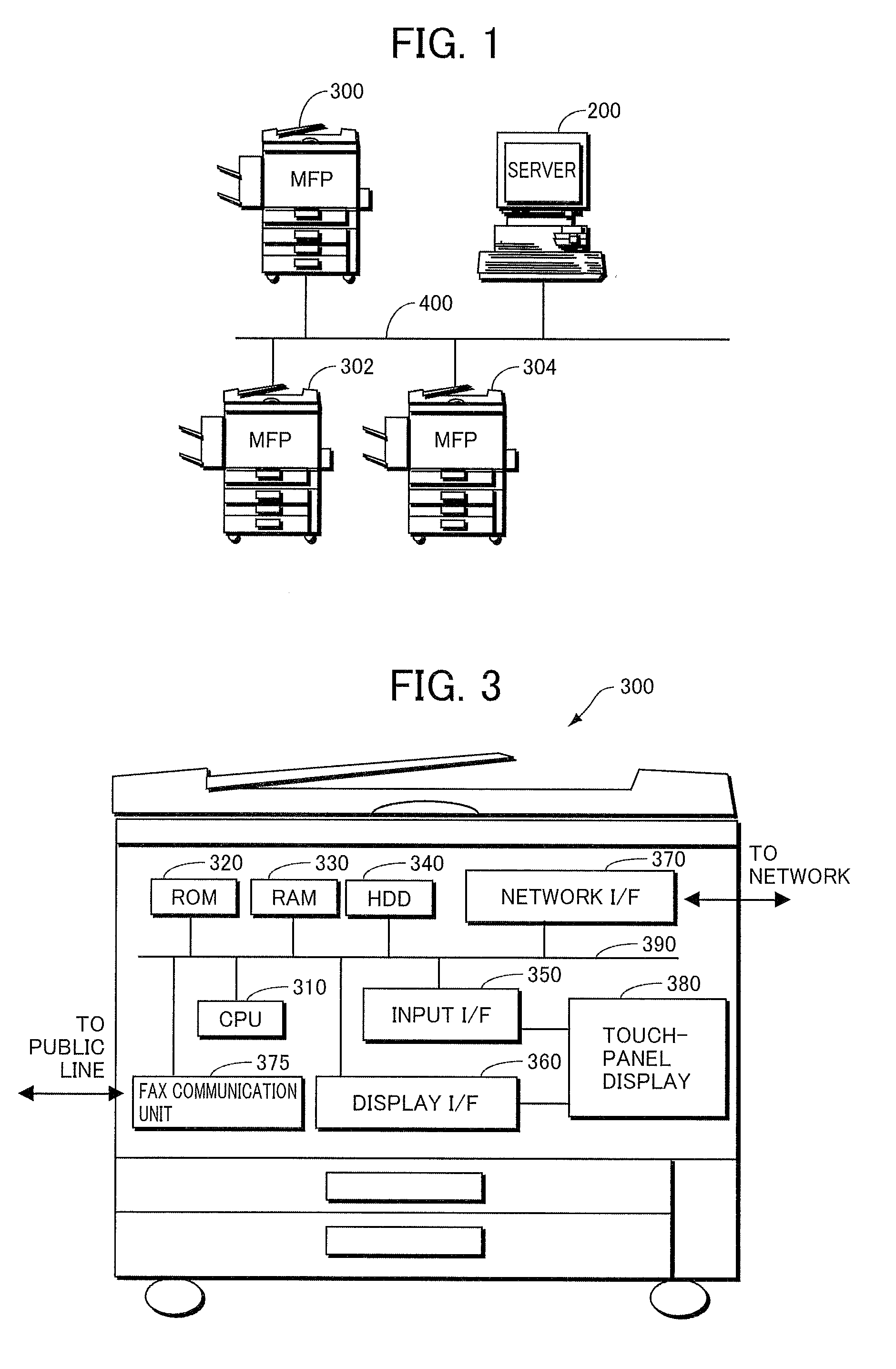
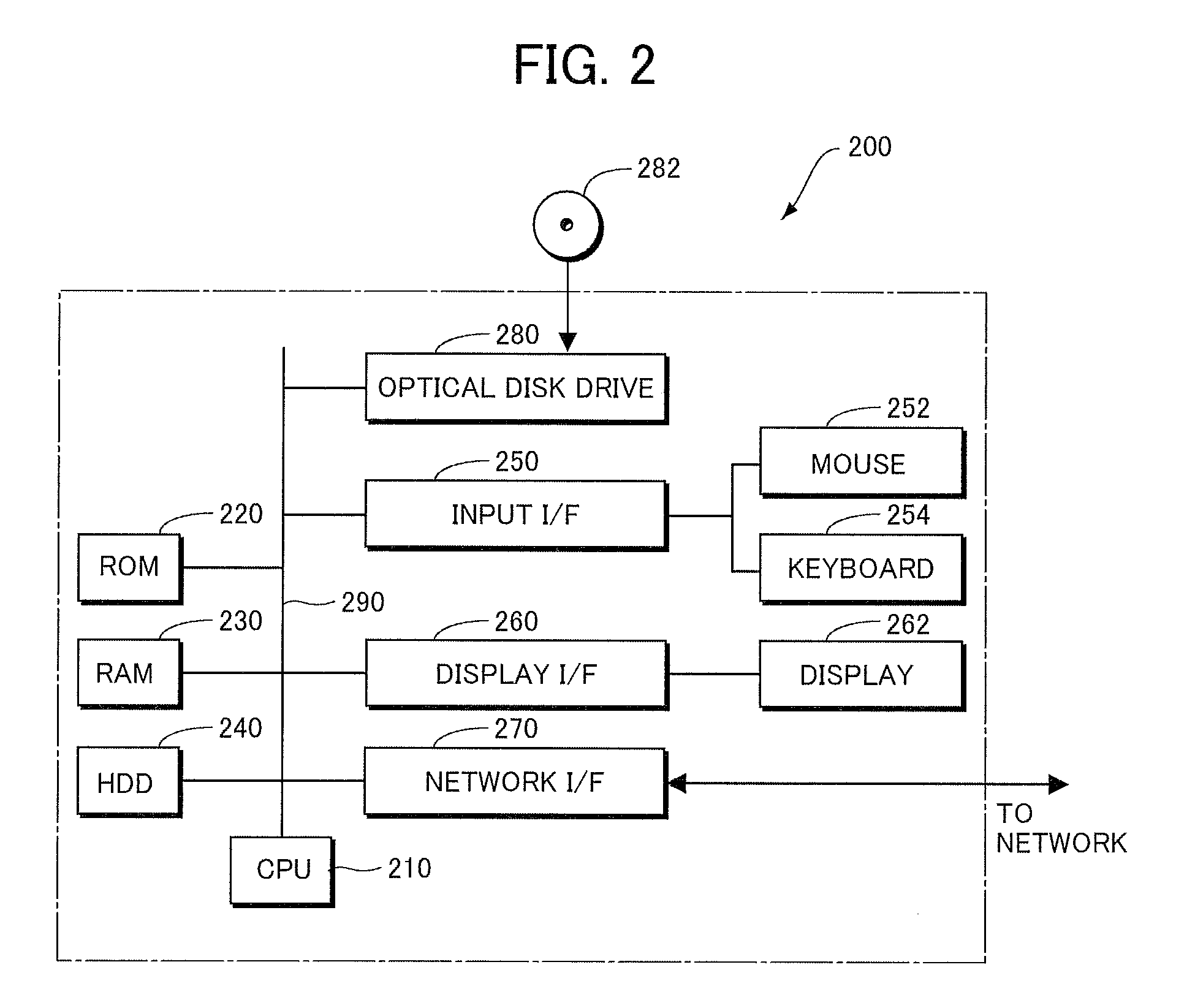
[0142]Server computer 200 and MFP 300 forming the network image forming system in accordance with the present embodiment have the same hardware configurations as server computer 200 and MFP 300 in accordance with the first embodiment described above. Therefore, figures related to the hardware are not newly provided, and the hardware configurations will be described with reference to FIGS. 2 and 3. The server computer and MFP forming the network image forming system in accordance with the present embodiment store management tables and execute programs that are partially different from those used in the first embodiment described above. In the present embodiment, as in the first embodiment, the useful information related to the destinations of multicast transmission may be given by a single MFP by itself, or the useful information related to the destinations of multicast transmission may be notified...


PUM


Abstract

An image communication apparatus includes: a display; an input device displaying an address input dialogue on the display, receiving a user input to designate an address of a transmission destination of multicast transmission; storage storing multicast transmission history; an extracting device, connected to the input device and the storage, responsive to the input device receiving an input of an address of a transmission destination of multicast transmission, for extracting, from the multicast transmission history, a multicast transmission history record including the address received by the input device as a transmission destination, and extracting an address different from the address received by the input device, included in the extracted multicast transmission history record, as a candidate of multicast transmission destination; and a control device controlling the display such that the extracted candidate of multicast transmission destination is displayed in the address input dialogue.

Description

CROSS-REFERENCE TO RELATED APPLICATION[0001]This nonprovisional application claims priority under 35 U.S.C. §119(a) on Patent Application No. 2009-159893 filed in Japan on Jul. 6, 2009, the entire contents of which are hereby incorporated by reference.BACKGROUND OF THE INVENTION[0002]1. Field of the Invention[0003]The present invention relates to an image communication apparatus represented by a facsimile apparatus and having multicast transmission (multi-address transmission) function of transmitting image data to a plurality of designated transmission destinations in response to one transmission request and, more specifically, to an image communication apparatus capable of easily and highly flexibly designating destinations of multicast transmission. The present invention also relates to an image forming apparatus including such an image communication apparatus.[0004]2. Description of the Background Art[0005]It has become increasingly common to connect an image forming apparatus h...

Claims


Application Information

Patent Timeline
IPC IPC(8): G06F3/12
CPCH04N1/00222H04N2201/0094H04N1/0035H04N1/00411H04N1/00413H04N1/00424H04N1/00427H04N1/00437H04N1/00474H04N1/00517H04N1/32037H04N1/32069H04N1/3209H04N1/32096H04N2201/0039H04N1/00244
Inventor OKADA, MIKIYA
Owner SHARP KK
Why Eureka
Try Eureka