Electric rotary actuator

a technology of electric rotary actuators and actuators, which is applied in the direction of electrical equipment, dynamo-electric machines, supports/enclosements/casings, etc., can solve the problems of difficult to obtain the required heat dissipation effect and reduce heat dissipation performance, so as to improve the heat dissipation effect and reduce the axial size and weight

Inactive Publication Date: 2011-09-15
JTEKT CORP
View PDF4 Cites 5 Cited by
  • Summary
  • Abstract
  • Description
  • Claims
  • Application Information

AI Technical Summary

Benefits of technology

[0008]The invention is made in the light of the above-described circumstances, and it is an object of the invention to provide an electric rotary actuator that, when an outer rotor electric motor is employed, is able to improve the heat dissipation effect while reducing the axial size and the weight.

Problems solved by technology

Therefore, when the thickness of the motor cover is reduced in order to reduce the axial size and the weight, heat dissipation performance decreases, so it is difficult to obtain a required heat dissipation effect.

Method used


Image

  • Electric rotary actuator
  • Electric rotary actuator
  • Electric rotary actuator

Examples


Embodiment Construction

[0019]Hereinafter, embodiments of the invention will be described with reference to the accompanying drawings.

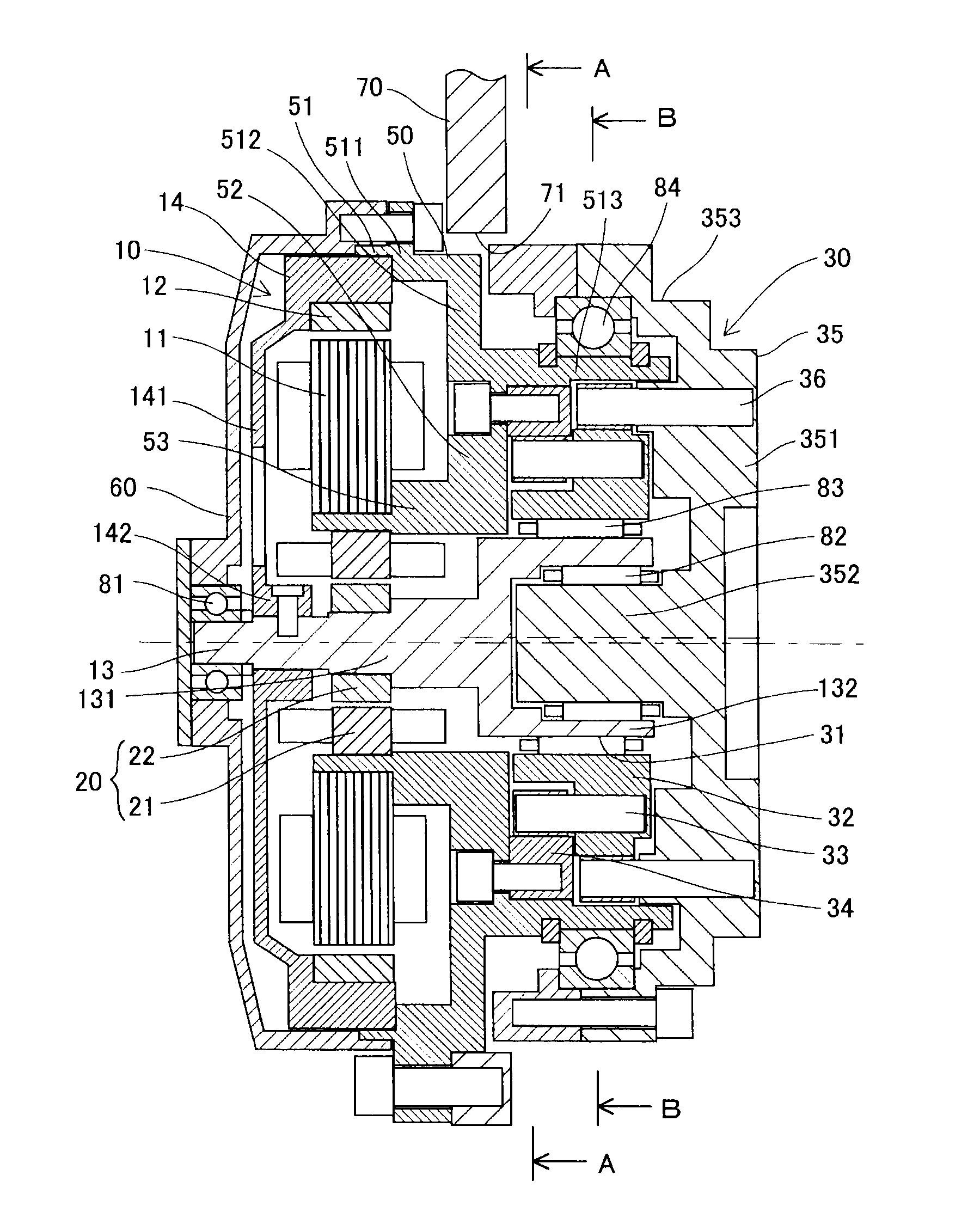
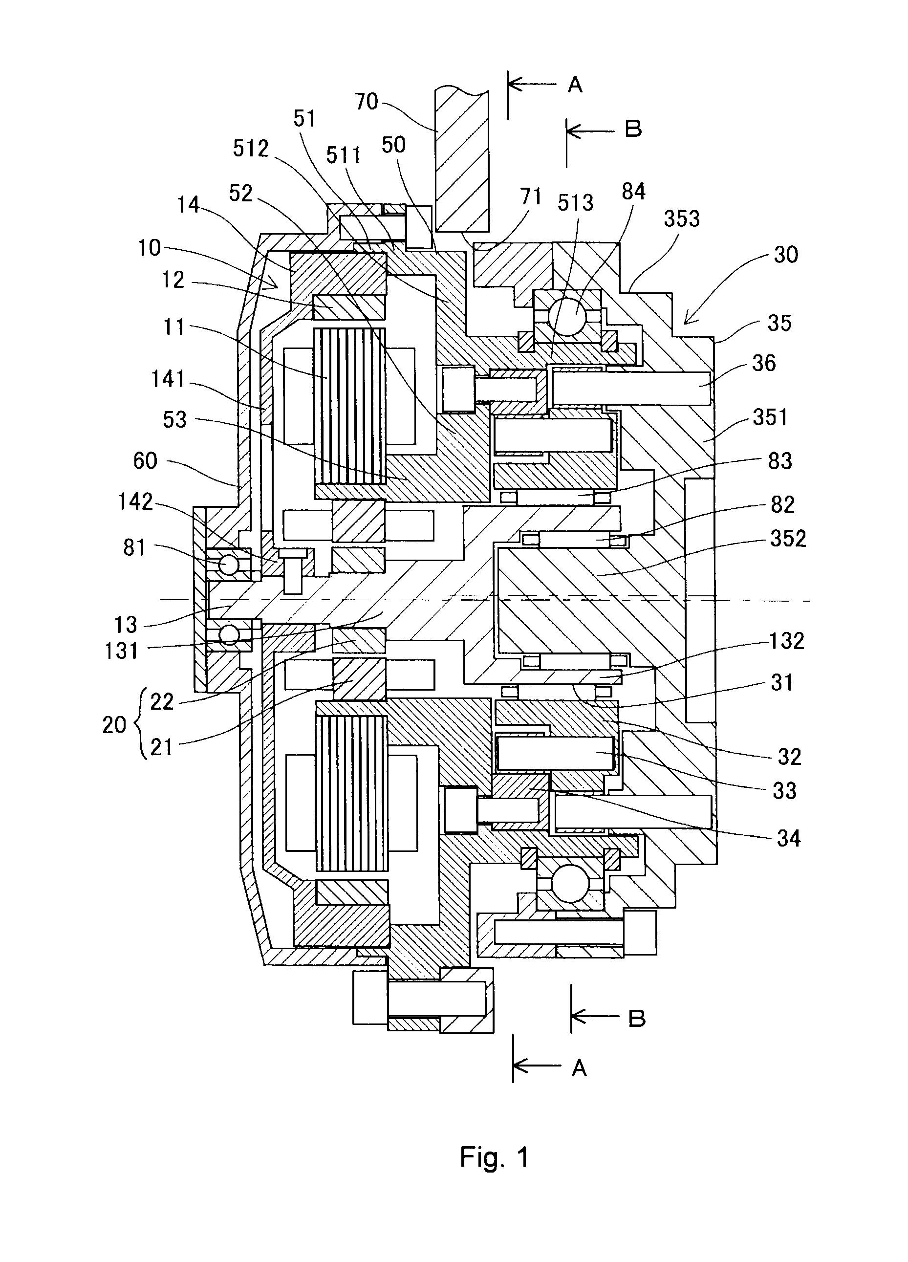
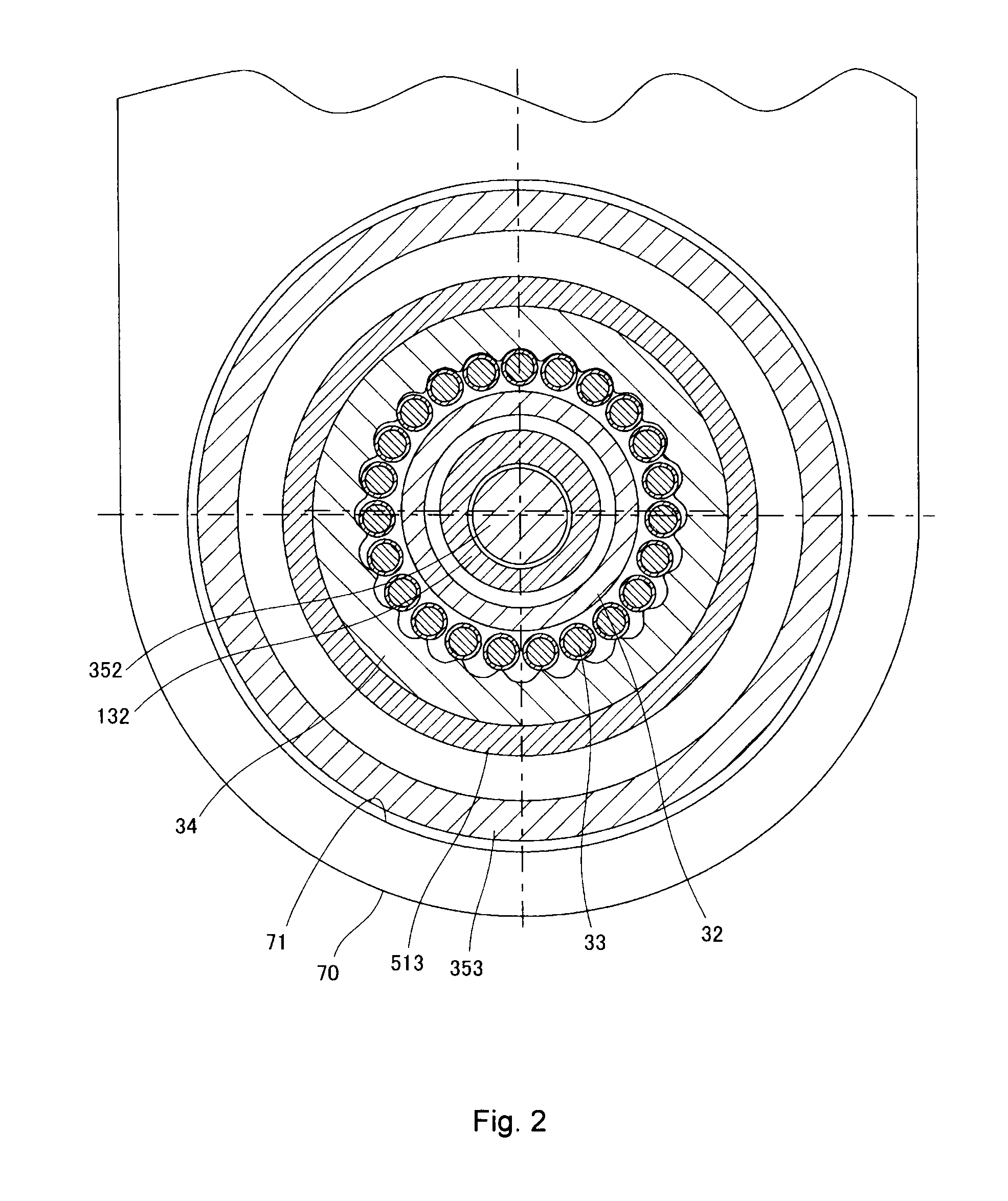
[0020]Hereinafter, an embodiment of an electric rotary actuator according to the invention will be described with reference to FIG. 1 and FIG. 2. As shown in FIG. 1, the electric rotary actuator includes an electric motor 10, a rotation angle detector 20, a speed reducer 30, a housing 50, a motor cover 60 and a support body portion 70. The rotation angle detector 20 detects the rotation angle of a motor output shaft 13 of the electric motor 10. The speed reducer 30 is integrally coupled to a one axial side portion (right side portion in FIG. 1) of the electric motor 10. The housing 50 accommodates part of the electric motor 10 and speed reducer 30.

[0021]The housing 50 is made of a metal having a high thermal conductivity, such as aluminum and steel. The housing 50 has a housing body 51, a partition wall portion 52 and a housing boss portion 53. The housing body 51 has a step...


PUM


Abstract

A housing is provided with a partition wall portion that partitions an inner space of the housing into an electric motor accommodating space and a speed reducer accommodating space. The partition wall portion fixes a gear that constitutes a speed reducer. In addition, the partition wall portion has a housing boss portion, and an inner stator is fixed to the housing boss portion. Thus, heat generated by the inner stator is dissipated to the outside through the housing boss portion and the partition wall portion.

Description

INCORPORATION BY REFERENCE / RELATED APPLICATION[0001]This application claims priority to Japanese Patent Application No. 2010-057000 filed on Mar. 15, 2010 the disclosure of which, including the specification, drawings and abstract, is incorporated herein by reference in its entirety.BACKGROUND OF THE INVENTION[0002]1. Field of the Invention[0003]The invention relates to an electric rotary actuator that includes an electric motor and a speed reducer.[0004]2. Discussion of Background[0005]In related art, there is an actuator that employs an outer rotor electric motor as described in Japanese Patent Application Publication No. 2004-274838 (JP-A-2004-274838) and Japanese Patent Application Publication No. 2008-6888 (JP-A-2008-6888). In an outer rotor electric motor, a stator that serves as a heat source is located on the inner side of a rotor. Therefore, it is important to ensure a heat dissipation path from the stator.[0006]The actuator described in JP-A-2004-274838 is formed so that f...

Claims


Application Information

Patent Timeline
Patent Type & Authority Applications(United States)
IPC IPC(8): H02K7/116
CPCH02K24/00H02K9/22H02K9/223
Inventor KATOH, YOSHINOBUNISHIMURA, YOSUKEANDO, ATSUSHI
Owner JTEKT CORP
Why Eureka
Try Eureka