Liquid ejecting head unit

a liquid ejector and head unit technology, applied in printing, inking apparatus, other printing apparatus, etc., can solve the problems of increasing the weight of the recording head, increasing the cost, and taking time to obtain an accurate liquid temperatur

Active Publication Date: 2012-04-19
SEIKO EPSON CORP
View PDF2 Cites 22 Cited by
  • Summary
  • Abstract
  • Description
  • Claims
  • Application Information

AI Technical Summary

Benefits of technology

[0019]According to this configuration, the temperature measurement device and the metal heat-transfer member can be strongly anchored to each other, which makes it possible to prevent the temperature measurement device and the metal heat-transfer member from separating from each other.

Problems solved by technology

Incidentally, in a recording head such as that described above, it takes time for heat to be transferred through the entirety of the metal and for the metal to reach a set temperature, and thus it takes time before an accurate liquid temperature can be obtained.
Furthermore, because the flow channel member is formed of a metal, it is difficult to form the flow channel member, and also leads to an increase in costs.
This also increases the weight of the recording head.

Method used


Image

  • Liquid ejecting head unit
  • Liquid ejecting head unit
  • Liquid ejecting head unit

Examples


Embodiment Construction

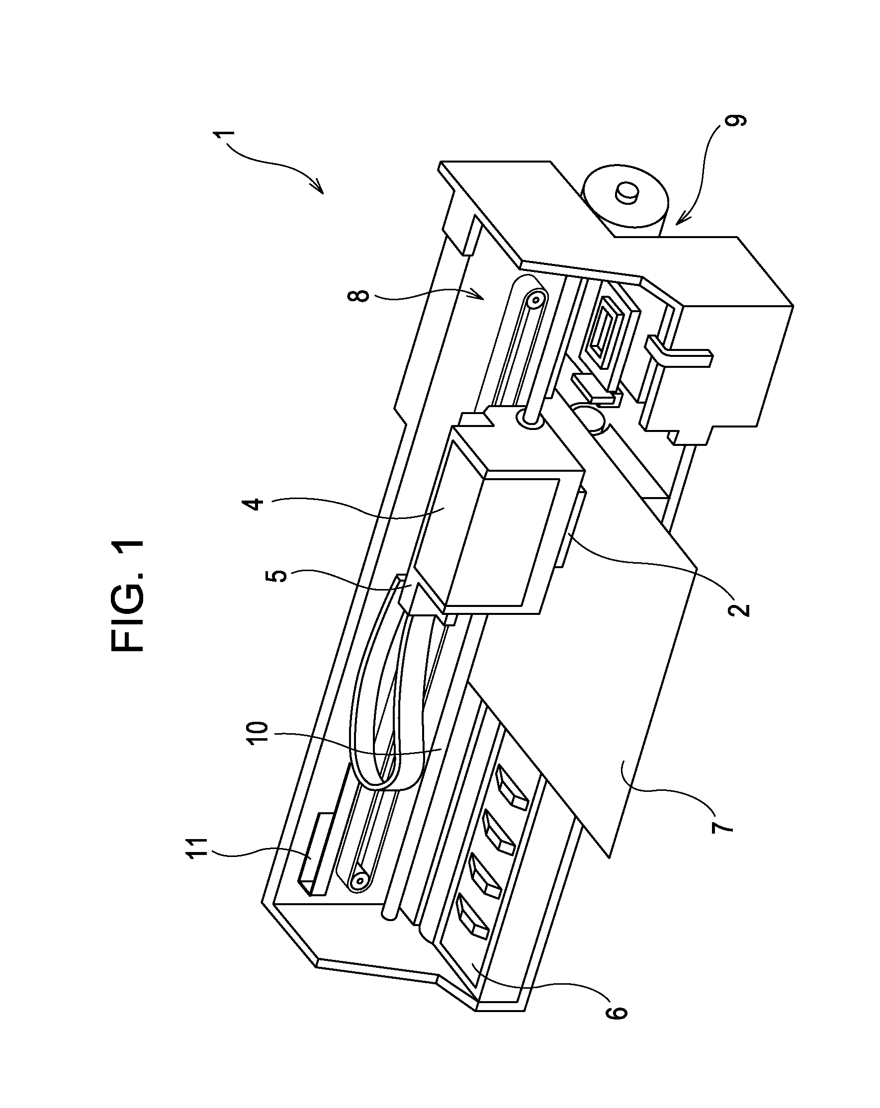
[0025]Hereinafter, embodiments of the invention will be described with reference to the appended drawings. Although various limitations are made in the embodiment described hereinafter in order to illustrate a specific preferred example of the invention, it should be noted that the scope of the invention is not intended to be limited to this embodiment unless such limitations are explicitly mentioned hereinafter. Hereinafter, an ink jet recording apparatus 1 (called simply a “printer” hereinafter) as illustrated in FIG. 1 will be described as an example of a liquid ejecting apparatus.

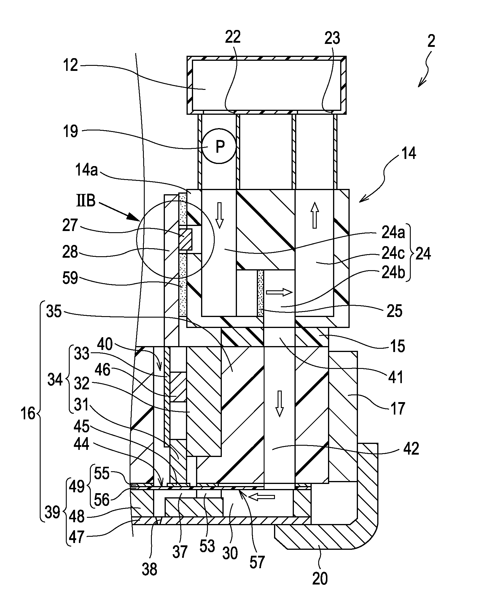
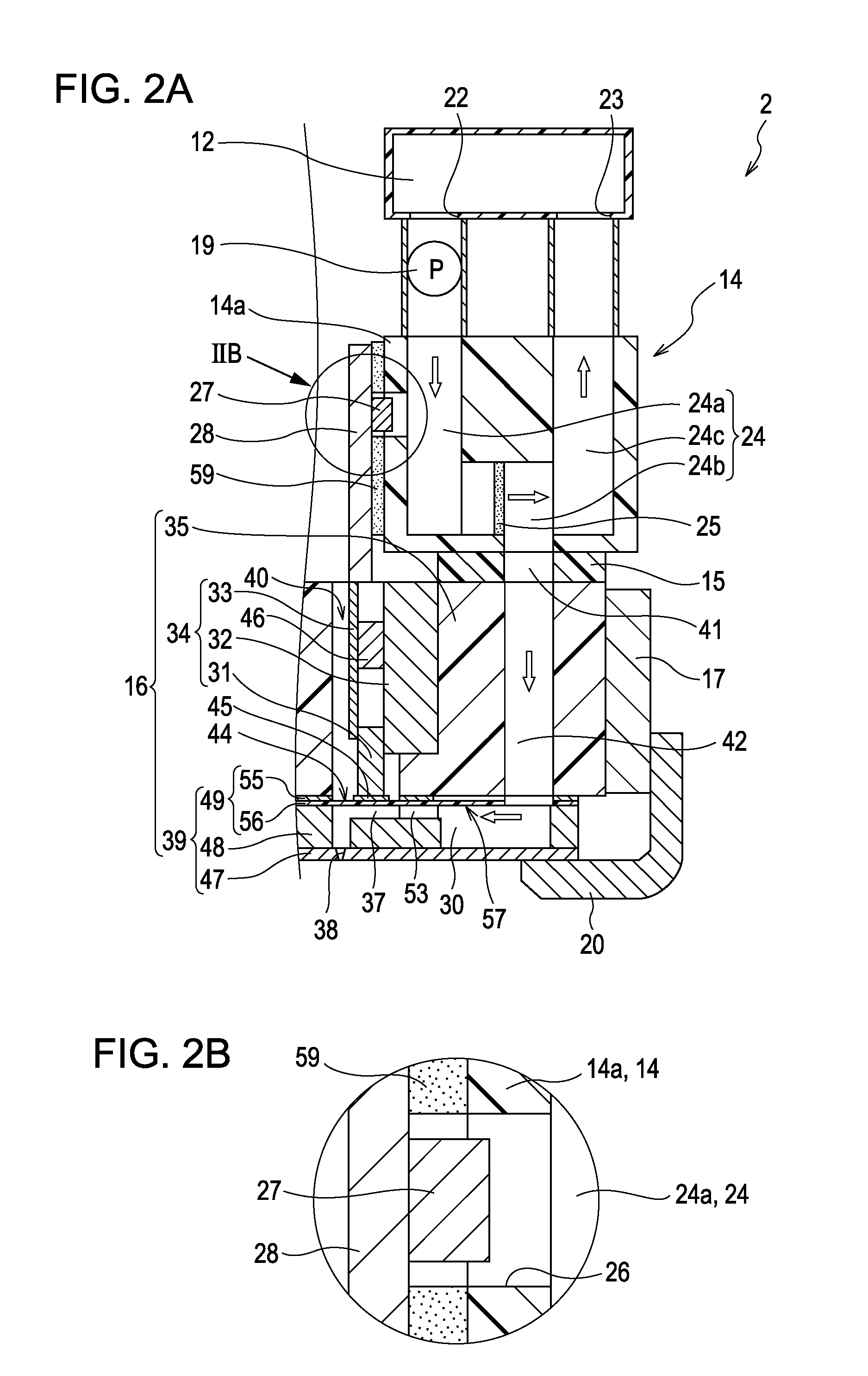
[0026]The printer 1 is provided with an ink jet recording head unit 2 (called simply a “recording head unit” hereinafter), serving as a type of liquid ejecting head unit, and the printer 1 is generally configured so as to include: a carriage 5 to which the recording head unit 2 and an ink cartridge 4 are attached; a platen 6 that is disposed below the recording head unit 2; a carriage movement mechanism...


PUM


Abstract

A liquid ejecting head unit includes: a liquid ejecting head that ejects a liquid through nozzles by driving a pressure generation element to cause the pressure within a pressure chamber to fluctuate; a flow channel member in which is formed a flow channel that supplies the liquid to a head flow channel of the liquid ejecting head; a substrate, mounted to a side surface of the flow channel member, on which is mounted an electrical component for supplying power to the pressure generation element; and a temperature measurement device provided on the surface of the substrate that faces the flow channel member. Here, the flow channel member includes an opening that passes therethrough toward the flow channel; and the temperature of the liquid within the flow channel is measured by the temperature measurement device that is provided facing the opening.

Description

[0001]The entire disclosure of Japanese Patent Application No: 2010-234247, filed Oct. 19, 2010 is expressly incorporated by reference herein.BACKGROUND[0002]1. Technical Field[0003]The present invention relates to a liquid ejecting head unit for an ink jet recording head or the like that applies pressure fluctuations to a pressure chamber that communicates with a nozzle and causes a liquid in the pressure chamber to be ejected through the nozzle.[0004]2. Related Art[0005]Ink jet recording heads (called simply “recording heads” hereinafter) used in image recording apparatuses such as ink jet recording apparatuses (called simply “printers” hereinafter), coloring material ejecting heads used in the manufacture of color filters for use in liquid-crystal displays and the like, electrode material ejecting heads used in the formation of electrodes in organic EL (electroluminescence) displays and FEDs (front emission displays) and the like, bioorganic matter ejecting heads used in the manu...

Claims


Application Information

Patent Timeline
Patent Type & Authority Applications(United States)
IPC IPC(8): B41J29/38
CPCB41J2/04528B41J2/04531B41J2/04563B41J2202/12B41J2/14274B41J2202/08B41J2/04581
Inventor YAMAMORI, AKIOUEZAWA, HARUHISA
Owner SEIKO EPSON CORP
Why Eureka
Try Eureka