Automatic video delay correction method

Inactive Publication Date: 2012-06-28
ABA ELECTRONICS TECH
View PDF3 Cites 0 Cited by
  • Summary
  • Abstract
  • Description
  • Claims
  • Application Information

AI Technical Summary

Benefits of technology

[0017]A primary object of the present invention is to provide an automatic video delay correction method. By means of this method, the video signals received by a remote-end receiving device can be automatically adjusted to synchronously display the three primary color signal in the video signal and overcome the problem of affection of the environmental factors (such as weather, humidity and aging of the cable material).
[0018]A further object of the present invention is to provide the above automatic video delay correction method. By means of this method, it is no more necessary for an operator to frequently check and adjust the picture displayed on the remote-end receiving device. Accordingly, the adjustment process can be more conveniently performed.
[0019]A still further object of the present invention is to provide the above automatic video delay correction method. By means of this method, the adjustment process is simplified so that the adjustment time is shortened.

Problems solved by technology

As a result, the video signals are likely to be distorted.
Moreover, the length of the signal transmission cable is limited to several meters.
In the case that the length of the signal transmission cable exceeds the range, the video signals will attenuate to lead to delay between the three primary color (R.G.B.) signals in the video signals.
This will result in vagueness, smear or color offset of the picture displayed on the remote-end receiving device.
However, the effect is limited.
It is hard for a user to precisely adjust the three primary color (R.G.B.) signals of the video signals to synchronously truly display the video signals.
It is impossible to adjust the colors of the video signals to be totally identical to the original colors of the transmitted video signals.
Moreover, the adjustment process is quite troublesome and complicated.
This leads to increase of labor cost and inconvenience in use of the device.
According to the aforesaid, the conventional technique has the following shortcomings:1. It is hard to precisely adjust the three primary color signals of the video signals to synchronously truly display the video signals.2. The adjustment process is quite troublesome and complicated.3. The signal transmission cable is subject to affection of various environmental factors so that a user needs to frequently adjust and correct the picture displayed on the remote-end receiving device.
This leads to increase of labor cost and inconvenience in use of the device.

Method used


Image

  • Automatic video delay correction method
  • Automatic video delay correction method
  • Automatic video delay correction method

Examples


Embodiment Construction

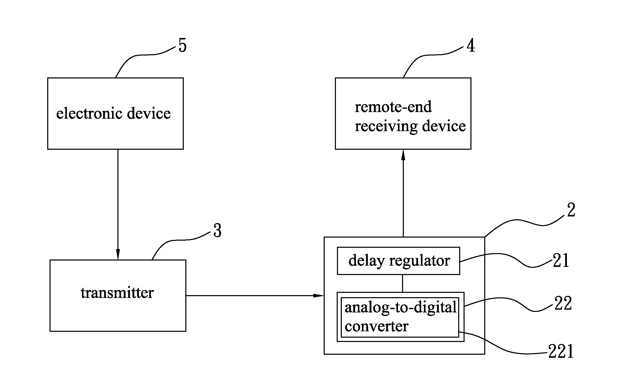
[0026]Please refer to FIGS. 2 and 3, which show a preferred embodiment of the automatic video delay correction method of the present invention. An automatic delay equalizer 2 is used in the method. The automatic delay equalizer 2 is connected to a transmitter 3 and co-used therewith. The transmitter 3 is connected with the automatic delay equalizer 2 via a first transmission cable L1 for transmitting signals (such as video signals). The first transmission cable L1 can be a CAT5 cable, a CAT5e cable or a CAT6 cable. In this embodiment, the first transmission cable L1 is a CAT5e cable for illustration purposes only.

[0027]One side of the transmitter 3 is connected to an electronic device 5, for example, a video player (such as a DVD player or a VCD player), a computer or a notebook via a third transmission cable L3. The other side of the transmitter 3 is connected with the first transmission cable L1. The transmitter 3 serves to receive a video signal transmitted from the electronic de...


PUM


Abstract

An automatic video delay correction method in which an automatic delay equalizer is used. The method includes steps of: using a processor to read a video signal and analyze and judge whether the back porch of the three primary color signal in a received video signal is the same; if not, using a delay regulator to automatically adjust the delay time of any two leading or trailing primary color signal to generate an adjusted back porch of two primary color signal; using the processor to compare the adjusted back porch of the two primary color signal with the back porch of a maximum delay time to judge whether the adjusted back porch is the same as the back porch of the maximum delay time; and if so, using the processor to generate an adjusted video signal and transmit the adjusted video signal to a remote-end receiving device.

Description

[0001]This application claims the priority benefit of Taiwan patent application number 099146275 filed on Dec. 28, 2010.FIELD OF THE INVENTION[0002]The present invention relates to an automatic video delay correction method. By means of this method, the video signals received by a remote-end receiving device can be automatically adjusted to synchronously and conveniently display the three primary color signal in the video signal.BACKGROUND OF THE INVENTION[0003]In a public site such as an airport, a metro train and a theater, a remote-end receiving device such as an electronic signboard, a television, etc. is connected to an electronic device at the other end, (such as a DVD player, a computer and a notebook), via a signal transmission cable. The video signals output from the electronic device are transmitted to the remote-end receiving device via the signal transmission cable for the remote-end receiving device to play the received video signals.[0004]However, a common signal trans...

Claims


Application Information

Patent Timeline
IPC IPC(8): H04N17/02
CPCH04N17/02
InventorHO, CHIH-CHUNHO, CHIH-YUAN
OwnerABA ELECTRONICS TECH