Peripheral illumination device for a vehicle component

a technology of peripheral illumination and vehicle components, which is applied in the direction of fixed installation, light and heating equipment, fibre light guides, etc., can solve the problems of mechanical failure of structural parts, inability to compensate for thermal expansion at such dimensions in the absence of additional measures, and the destruction or defect of interacting parts, etc., to achieve the effect of easy installation and production

Active Publication Date: 2013-03-07
AUDI AG
View PDF3 Cites 19 Cited by
  • Summary
  • Abstract
  • Description
  • Claims
  • Application Information

AI Technical Summary

Benefits of technology

[0021]In accordance with the present invention, a rectangular sunroof and / or sunroof section of a vehicle roof for example can now easily be produced and equipped with an illumination device because the provision of a peripheral illumination device according to the present invention is especially beneficial in the event of vehicle components of single-piece construction. The ends of the light guides and their light sources and pertaining coupling elements can generally be installed easily in the sunroof or vehicle roof.
[0022]According to another advantageous feature of the present invention, the peripheral illumination device may include four light guides for a rectangular sunroof. The light guides are hereby respectively associated to the four straight sides of the rectangle, with each light guide being firmly mounted halfway of the respective rectangle side along the enclosure and the two ends of the each light guide in length direction thereof being floatingly supported outside the rectangle in the vehicle roof together with the light sources and their coupling elements. The individual light guides are thus routed in the area of a frame of the rectangular sunroof in the adjacent vehicle roof. As a result, the presence of a breach in the illuminated border is avoided in the area of the corners of the peripheral illumination device and the impression of a peripheral and evenly illuminated border is conveyed to the vehicle occupant.

Problems solved by technology

As the illuminations are rigidly mounted to the structures that are illuminated, temperature stress is encountered, causing destruction or defects of the interacting parts.
Thermal expansions encountered at such dimensions cannot be compensated in the absence of additional measures.
Different building materials have varying thermal expansion coefficient, causing substantial differences in expansion when exposed to high or very low temperatures and ultimately leading to mechanical failure of the structural parts—e.g. rupture of a light guide—which in turn leads to malfunction of the structural parts or even to complete destruction.
Thus, conventional models and methods are inadequate to provide peripheral illumination of large-area vehicle components.

Method used


Image

  • Peripheral illumination device for a vehicle component
  • Peripheral illumination device for a vehicle component

Examples


Embodiment Construction

[0026]Throughout all the figures, same or corresponding elements may generally be indicated by same reference numerals. These depicted embodiments are to be understood as illustrative of the invention and not as limiting in any way. It should also be understood that the figures are not necessarily to scale and that the embodiments are sometimes illustrated by graphic symbols, phantom lines, diagrammatic representations and fragmentary views. In certain instances, details which are not necessary for an understanding of the present invention or which render other details difficult to perceive may have been omitted.

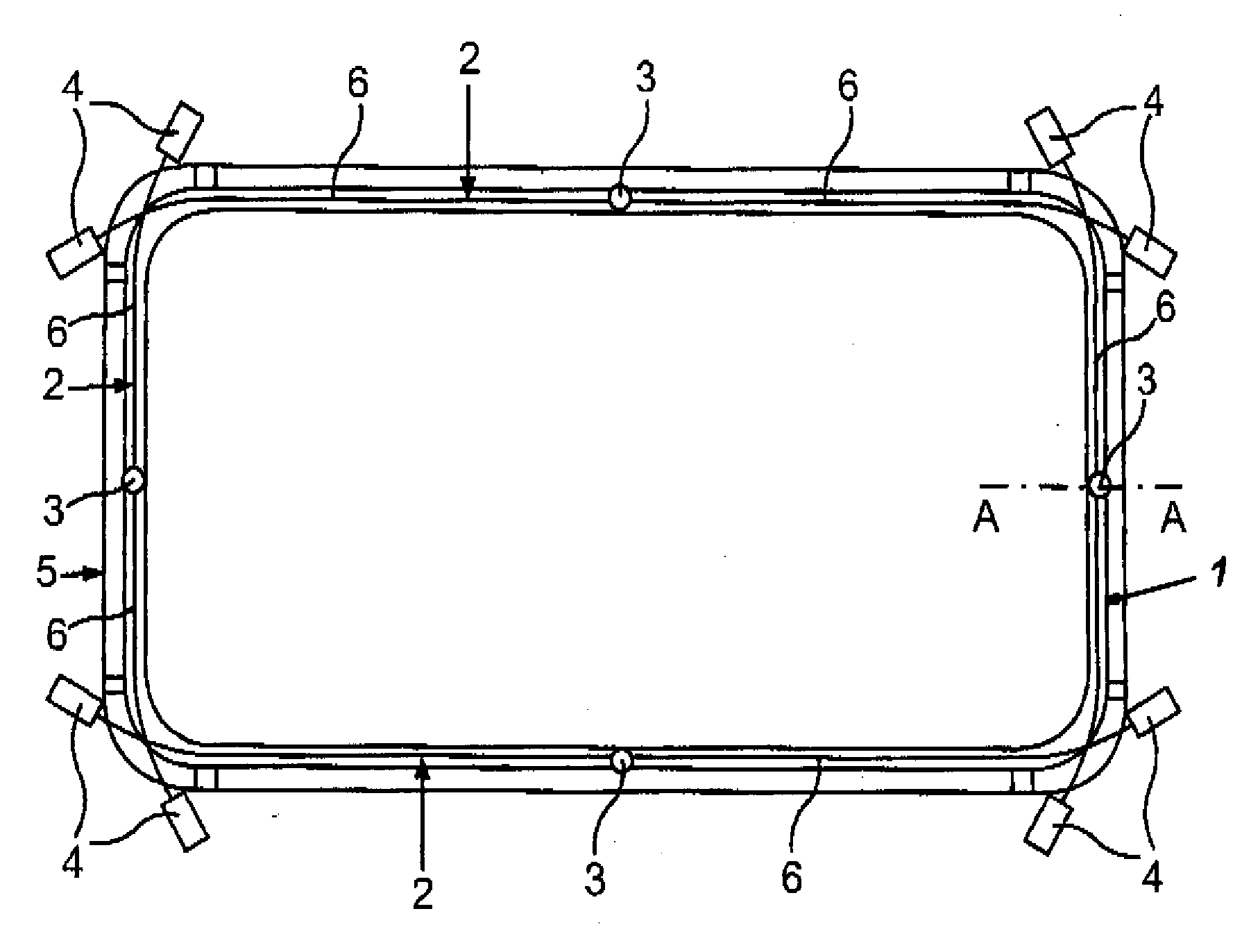
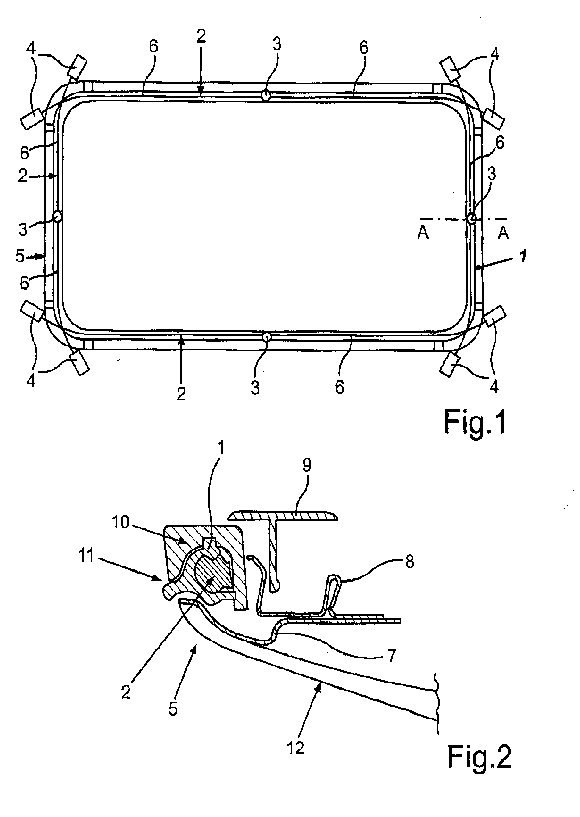
[0027]Turning now to the drawing, and in particular to FIG. 1, there is shown, by way of example, a schematic plan view of a section 5 of a rectangular sunroof in a vehicle roof, having incorporated therein a peripheral illumination device according to the present invention. The illumination device includes an enclosure 1 which extends along four sides of the rectangular sun...


PUM


Abstract

A peripheral illumination device for a vehicle component includes at least one light guide, and an enclosure for guiding the at least one light guide. The at least one light guide is securely mounted in the enclosure via a fixed support at a predefined location and has two ends which are movably mounted in relation to the enclosure.

Description

CROSS-REFERENCES TO RELATED APPLICATIONS[0001]This application claims the priority of German Patent Application, Serial No. 10 2011 112 320.6, filed Sep. 2, 2011, pursuant to 35 U.S.C. 119(a)-(d), the content of which is incorporated herein by reference in its entirety as if fully set forth herein.BACKGROUND OF THE INVENTION[0002]The present invention relates to a peripheral illumination device, especially for a vehicle component, and to a vehicle equipped with such a peripheral illumination device.[0003]The following discussion of related art is provided to assist the reader in understanding the advantages of the invention, and is not to be construed as an admission that this related art is prior art to this invention.[0004]Peripheral illumination is used to date for objects such as speakers, pushbuttons, cup holders, etc. Normally, this kind of illumination involves a ring-shaped Plexiglas light guide having typically incorporated therein two LEDs. The light guide is hereby rigidl...

Claims


Application Information

Patent Timeline
Patent Type & Authority Applications(United States)
IPC IPC(8): F21S8/10F21W107/10
CPCB60Q3/004G02B6/001B60Q3/0213B60Q3/64B60Q3/208
Inventor PFEIL, MARCUS
Owner AUDI AG
Why Eureka
Try Eureka