Wireless power transmitter and method of controlling the same

Active Publication Date: 2013-04-25
SAMSUNG ELECTRONICS CO LTD
View PDF2 Cites 39 Cited by
  • Summary
  • Abstract
  • Description
  • Claims
  • Application Information

AI Technical Summary

Benefits of technology

[0014]Therefore, the present invention has been made to solve the above-mentioned problems occurring in the prior art, and provide the advantages and improvements as will be descr

Problems solved by technology

However, when using such a contact charging method, the contacting terminals are susceptible to be contaminated by dirt because they extend outward, thus suffering from inappropriate charging.
Also, they may not be properly charged when exposed to moisture.
In this case, impedance at a particular point of the wireless power transmitter m

Method used


Image

  • Wireless power transmitter and method of controlling the same
  • Wireless power transmitter and method of controlling the same
  • Wireless power transmitter and method of controlling the same

Examples


Embodiment Construction

[0026]Hereinafter, embodiments of the present invention are described with reference to the accompanying drawings. In the following description, the same elements may be designated by the same reference numerals although they are shown in different drawings. Further, various specific definitions found in the following description are provided only to help general understanding of the present invention, and it is apparent to those skilled in the art that the present invention can be implemented without such definitions. Further, in the following description of the present invention, a detailed description of known functions and configurations incorporated herein may be omitted when such a description may obscure the subject matter of the present invention.

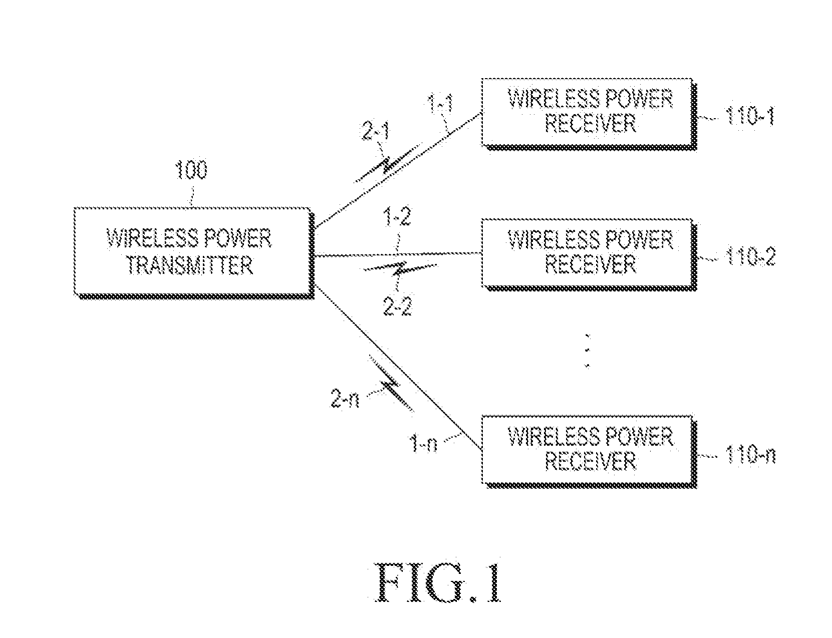
[0027]FIG. 1 is a diagram illustrating a wireless charging system according to an embodiment of the present invention.

[0028]Referring to FIG. 1, the wireless charging system includes a wireless power transmitter 100 and wireless pow...


PUM


Abstract

A method and a wireless power transmitter for transmitting charging power to a wireless power receiver are provided. The method includes applying the charging power to the wireless power receiver; determining whether a current value of the charging power is greater than a predetermined threshold; and driving the overcurrent protection circuit upon a determination that the current value of the charging power is greater than the predetermined threshold.

Description

PRIORITY[0001]This application claims priority under 35 U.S.C. §119(e) to a Provisional U.S. Patent Application filed in the USPTO on Oct. 24, 2011, and assigned Ser. No. 61 / 550,696, the entire content of which is incorporated herein by reference.BACKGROUND OF THE INVENTION[0002]1. Field of the Invention[0003]The present invention relates generally to a wireless power transmitter and method of controlling the same, and more particularly, to a wireless power transmitter for transmitting charging power to a wireless power receiver and method of controlling the same.[0004]2. Description of the Related Art[0005]Mobile terminals, such as cell phones, Personal Digital Assistants (PDAs), etc., are powered by rechargeable batteries, and in order to recharge the batteries, the terminals supply electric energy to the batteries via separate charging devices. Typically, the charging device and the battery each having contacting terminals on their respective outer surfaces, and are electrically ...

Claims


Application Information

Patent Timeline
IPC IPC(8): H02J7/00
CPCH02J7/0034H02J7/025H02J7/0004H02J50/40H02J50/12H02J50/80H02J7/00036H02J7/00047H02J7/00304H02J7/04
Inventor PARK, SE-HOPARK, SUNG-BUMYEO, SUNG-KU
Owner SAMSUNG ELECTRONICS CO LTD
Why Eureka
Try Eureka