Push/Pull Rotary Cutting Apparatus Driven By Substrate

a cutting device and substrate technology, applied in the field of rotary cutting devices, can solve the problems of poor insulating qualities, limited use in factory or shop setting, intricate design of cutting devices, etc., and achieve the effects of low cost, simple design, and lightweigh

Inactive Publication Date: 2013-08-29
BUSS RICHARD S
View PDF17 Cites 2 Cited by
  • Summary
  • Abstract
  • Description
  • Claims
  • Application Information

AI Technical Summary

Benefits of technology

[0027]An advantage of the present invention is an improved fiberglass insulation cutting apparatus that overcomes some of the problems and shortcomings of the prior art.
[0028]Another advantage of the present invention is an improved fiberglass cutting apparatus that is simplistic in design and available at relatively low cost.
[0029]Another advantage of the present invention is an improved fiberglass cutting apparatus that is portable, lightweight, durable, and useful at home or on construction sites.
[0030]Another advantage of the present invention is an improved fiberglass cutting apparatus such that fiberglass insulation may be cut to varying widths quickly, efficiently, and without waste of material at nonfactory settings.
[0031]Another advantage of the present invention is an improved fiberglass cutting apparatus that minimizes respiratory hazards associated with airborne fiberglass fibers.

Problems solved by technology

Material waste, code violations, and poor insulating qualities may result if the insulation is not cut properly.
Such devices cut insulation at a desired length and constant width, but are, for the most part, limited in use to factory or shop setting because of their large size and stationary nature.
Generally, these cutting devices are motorized and intricate in design.
However, for several pieces of fiberglass of a unique length and width, as are often needed at a construction site, the use of cutting devices of the prior art is substantially less than satisfactory, in terms of cost effectiveness and their considerable size.
They are even less satisfactory for home use by the weekend warrior who does it himself or herself.
One approach, which is widespread but of limited success, is the use of a blade in conjunction with a straight edge cutting guide.
One major problem is that these devices of the prior art rarely provide the desired cut.
The result is a piece of fiberglass insulation not cut as measured and apt to provide poor insulation qualities.
The inefficient use of material is obviously a short term problem.
In the long term, higher heating bills continue to add to the economic cost.
Another significant problem is that the blades of the prior art tend to tear through the insulation.
A side effect is that insulation fibers often become airborne and pose a respiratory hazard to any worker close by.
In summary, a considerable number of drawbacks and problems exist in the art relating to fiberglass insulation cutting devices.

Method used


Image

  • Push/Pull Rotary Cutting Apparatus Driven By Substrate
  • Push/Pull Rotary Cutting Apparatus Driven By Substrate
  • Push/Pull Rotary Cutting Apparatus Driven By Substrate

Examples


Embodiment Construction

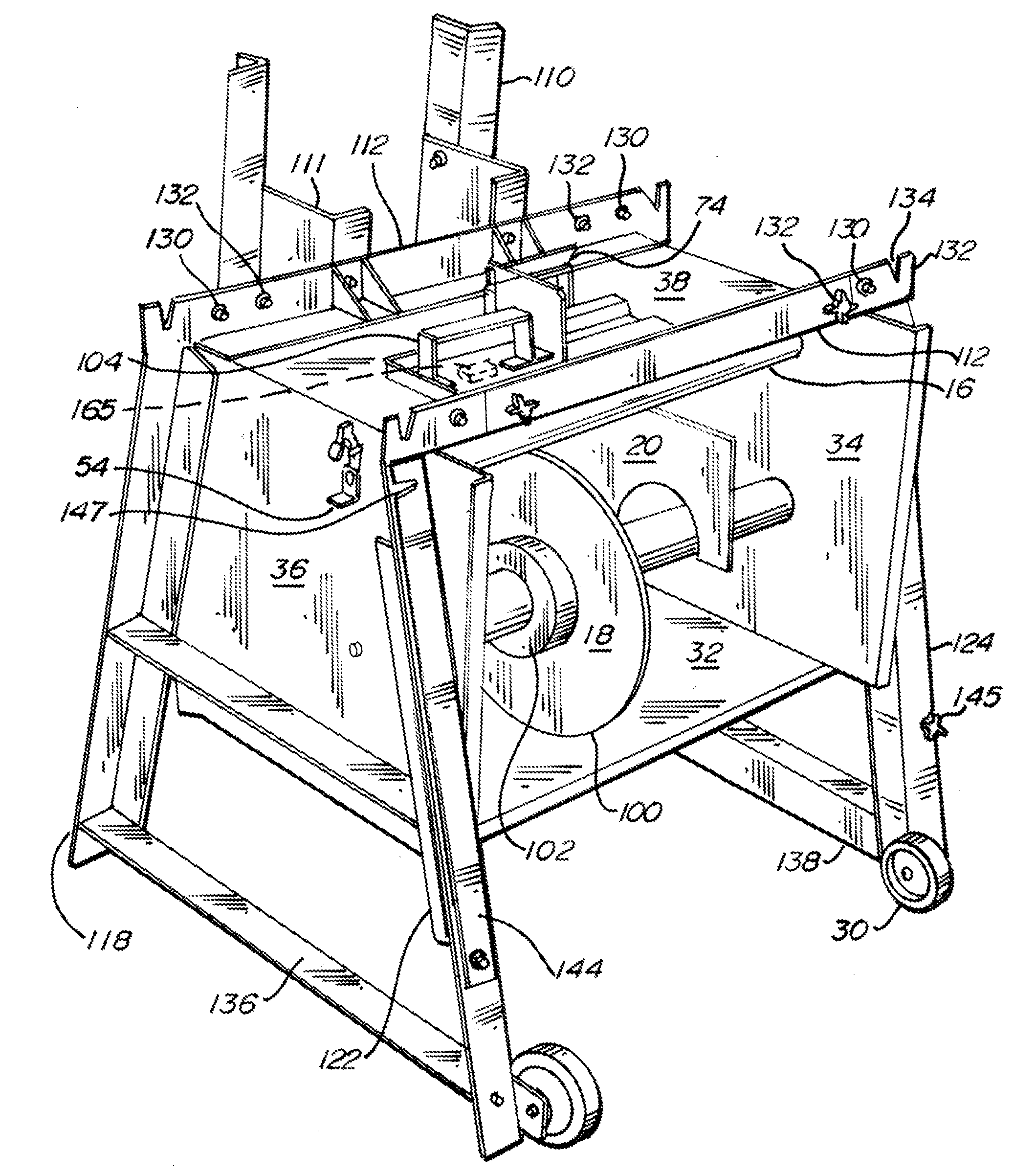
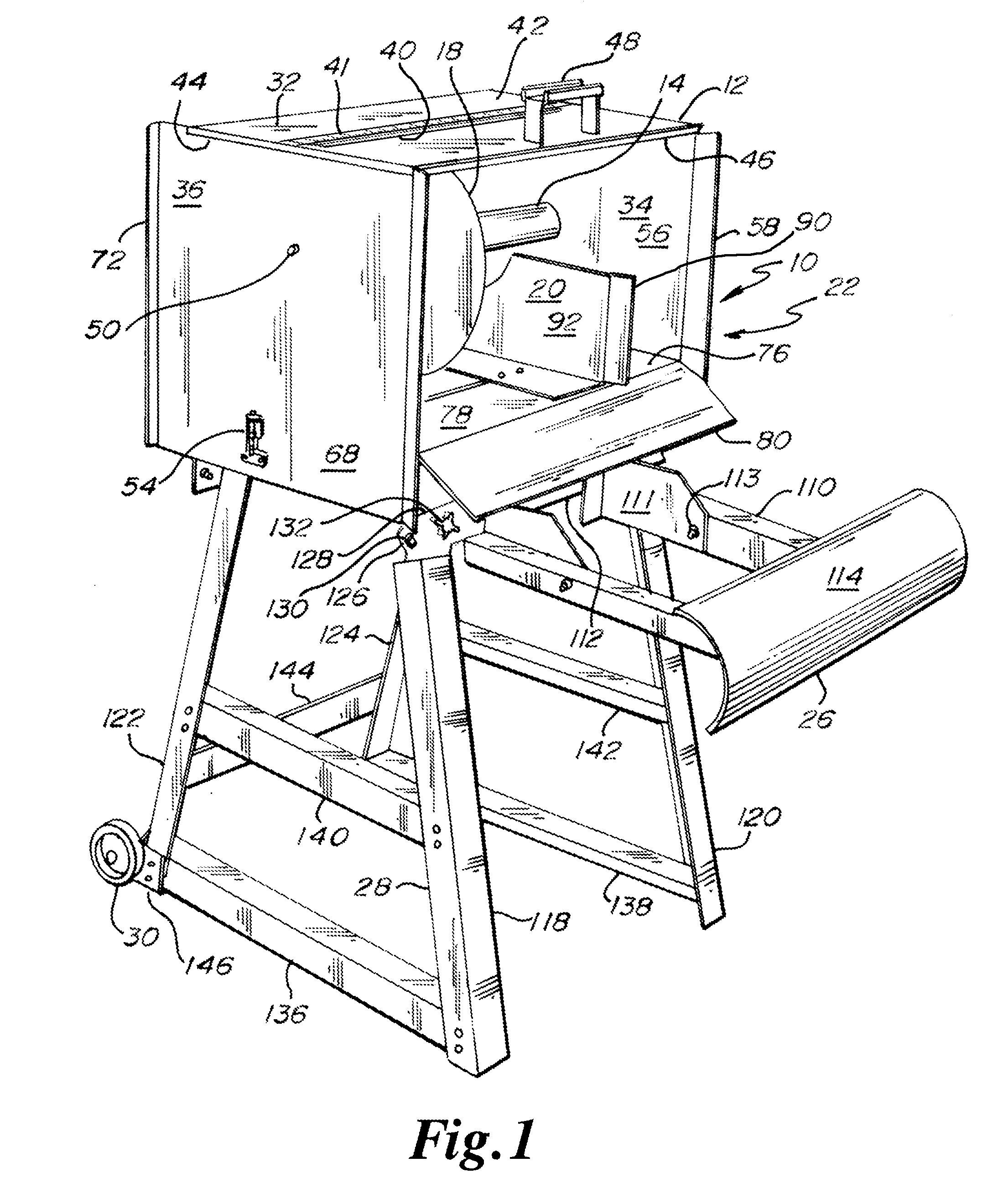
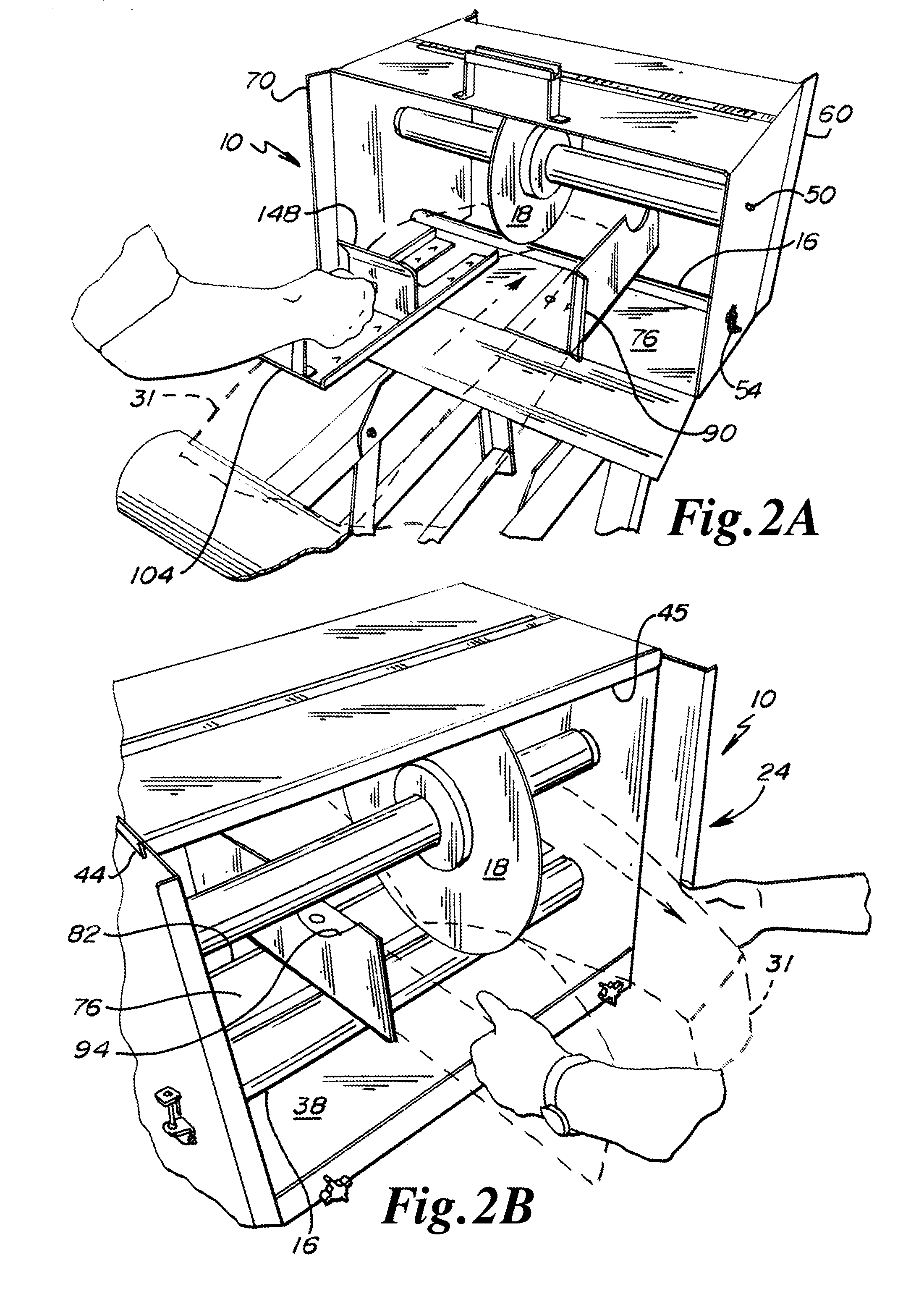
[0046]As shown in FIGS. 1, 2A and 2B, the present rotary cutting apparatus is designated by reference numeral 10. Rotary cutting apparatus 10 generally includes a housing 12, an upper first roller 14 engaged to the housing 12, a lower second roller 16 engaged to the housing 12, a rotary or circular blade 18 engaged to the first roller 14 and engaging the second roller or rolling anvil 16, a fence 20 engaged to the housing 12 and being adjustable to and away from the rotary blade 18, an inlet 22, an outlet 24, a feed transition member 26 engaged to the housing 12, legs 28 supporting the housing 12, and a pair of wheels 30. The preferred substrate 31 for the rotary cutting apparatus 10 is fiberglass insulation batting, shown in FIGS. 2A, 2B and 4D.

[0047]Housing or frame 12 is a box or box like structure having a horizontally extending top 32, vertically extending first side 34, vertically extending second side 36, and horizontally extending bottom 38. Housing 12 further includes the i...


PUM

PropertyMeasurementUnit
sizeaaaaaaaaaa
thickaaaaaaaaaa
widthaaaaaaaaaa

Abstract

An apparatus for cutting fiberglass insulation batting with a rotary blade where an elongate section of fiberglass insulation batting is manually pushed into an inlet of the apparatus whereupon the blade bites into the fiberglass insulation batting and whereupon the elongate now split section of fiberglass insulation batting begins to protrude from the outlet of the apparatus, whereupon the protruding sections of fiberglass insulation batting are manually grabbed and pulled through the apparatus further driving the rotary blade and further cutting the fiberglass insulation batting.

Description

[0001]This application is a continuation of U.S. patent application Ser. No. 12 / 575,955 filed Oct. 8, 2009 and claims the benefit thereof under 35 U.S.C. §120. U.S. patent application Ser. No. 12 / 575,955 filed Oct. 8, 2009 further claims the benefit under 35 U.S.C. §119(e) of U.S. Provisional Patent Application No. 61 / 195,545 filed on Oct. 9, 2008. U.S. patent application Ser. No. 12 / 575,955 filed Oct. 8, 2009 and U.S. Provisional Patent Application No. 61 / 195,545 filed Oct. 9, 2008 are hereby incorporated by reference in their entireties into this application.FIELD OF THE INVENTION[0002]The present invention generally relates to a rotary cutting apparatus, particularly to a rotary cutting apparatus that is driven by the substrate itself, and specifically to a rotary cutting apparatus that is driven by a fiberglass insulation batting substrate being pushed into and pulled out of the apparatus.BACKGROUND OF THE INVENTION[0003]Installation of fiberglass insulation is often part of num...

Claims


Application Information

Patent Timeline
Patent Type & Authority Applications(United States)
IPC IPC(8): B26D5/38
CPCB26D1/15B26D5/38B26D5/20B26D1/22Y10T83/6584Y10T83/6592Y10T83/727Y10T83/7793Y10T83/872Y10T83/8745
Inventor BUSS, RICHARD S.
Owner BUSS RICHARD S
Why Eureka
Try Eureka