Method and device for obtaining a continuous movement of a display means

a display means and continuous movement technology, applied in the field of display devices, can solve the problems of not being able to overcome the jerky movement of hands, not providing a mechanism for slowing down the scrolling of the counter used for correction, and still lacking smoothness in slowing down the scrolling speed, so as to improve the smoothness of adjustment, improve the efficiency of adjustment operation, and improve the effect of scrolling speed

Active Publication Date: 2013-10-03
THE SWATCH GRP RES & DEVELONMENT LTD
View PDF14 Cites 26 Cited by
  • Summary
  • Abstract
  • Description
  • Claims
  • Application Information

AI Technical Summary

Benefits of technology

[0012]One advantage of the proposed solution is that it makes any adjustment operation more efficient and visually more intuitive by emulating a newtonian motion for the display means, i.e. wherein velocity is continuous with acceleration and deceleration proportional to an applied force or torque. It is therefore possible to adjust the scrolling speed to the magnitude of the correction, by first of all performing a rough adjustment and then a finer adjustment, when close to the desired value, at a velocity that remains continuous.
[0013]An additional advantage of the proposed solution is that it does not require any particular sensor resolution for incrementing the display values. Smoothness of adjustment is ensured in particular by the fact that it is the acceleration of the display member which is deduced from the motions of a control member or detected by a sensor, and not a correction velocity. This thus generates a continuous velocity of the display member, in conformity with the motion of a mechanical member according to newton's laws of physics. This velocity has only small variations between different control member

Problems solved by technology

Moreover, no correction occurs between two successive movements of the crown, and no mechanism is provided for slowing down the scrolling of the counter used for correction.
On the one hand this is inconvenient, and on the other hand it does not overcome the jerky movement of the hands.
However, this slowing down of the scrolling

Method used


Image

  • Method and device for obtaining a continuous movement of a display means
  • Method and device for obtaining a continuous movement of a display means
  • Method and device for obtaining a continuous movement of a display means

Examples


Embodiment Construction

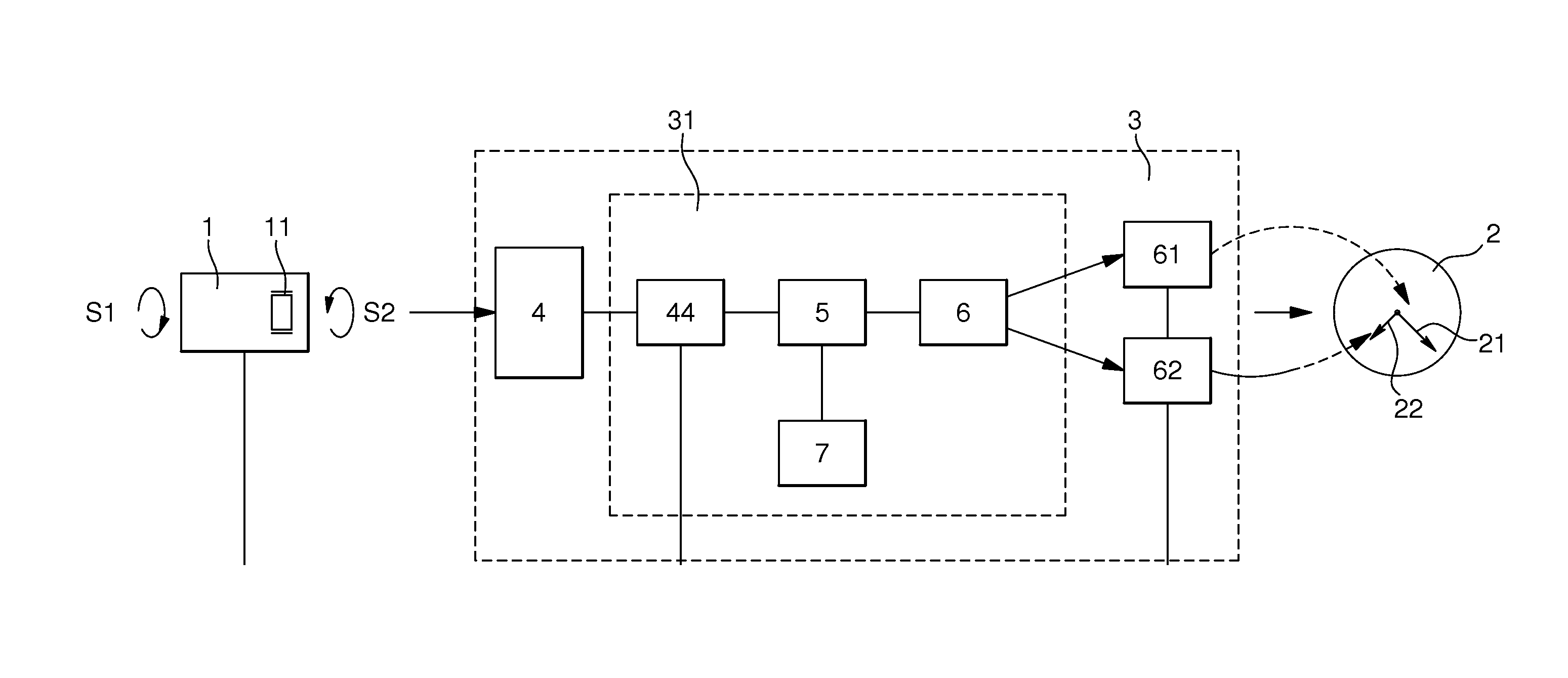
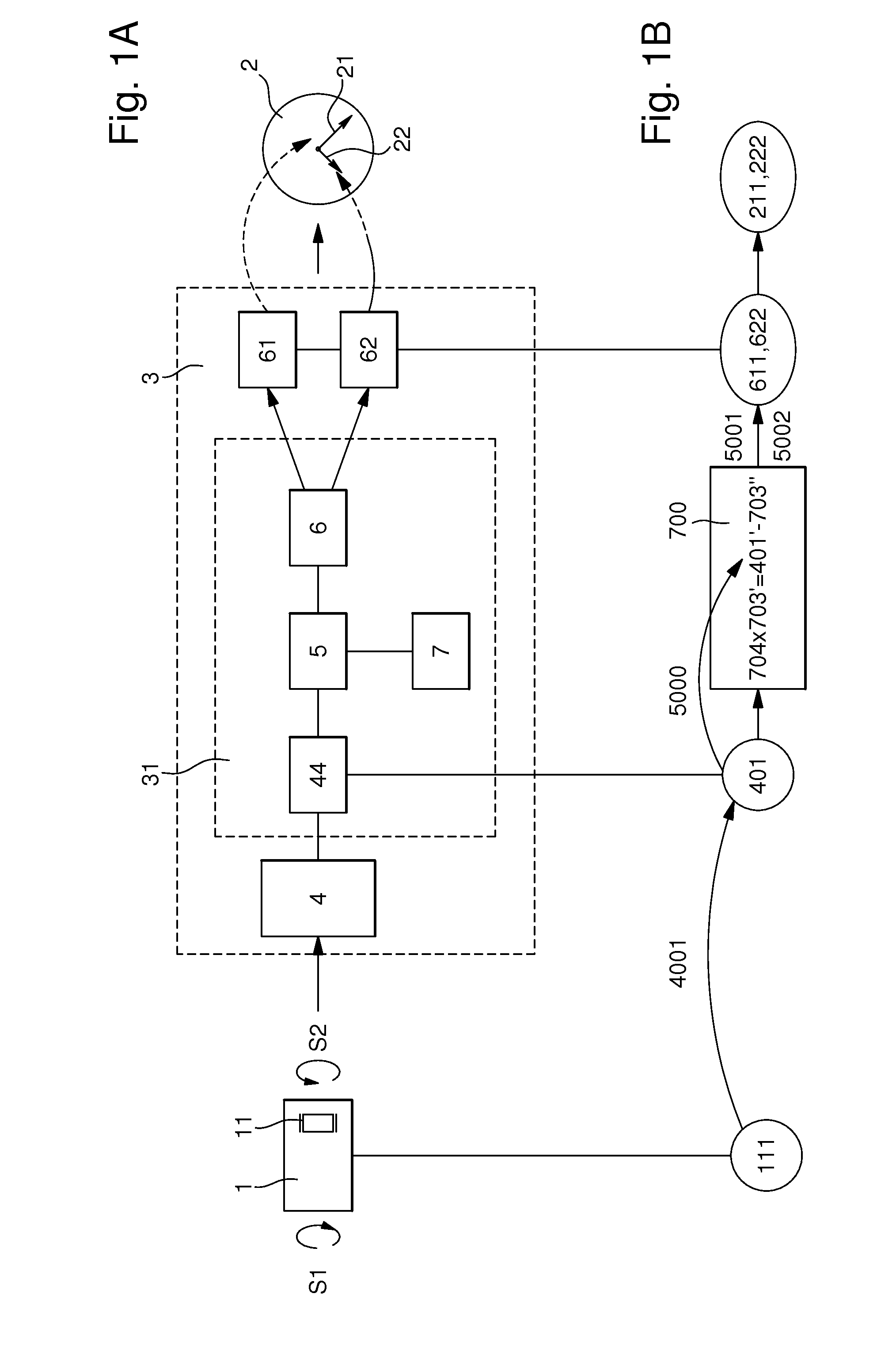
[0025]A preferred embodiment of the control device of the invention is intended for timepieces and is illustrated in FIGS. 1A and 1B, which respectively show the logic structure of control device 3 and the various parameters used and the different calculation steps performed by various elements of control device 3 to convert the motion of actuation means 1 into a non-proportional motion of the display means, unlike a conventional mechanical gear train. FIG. 1A shows the preferred structure of actuation means 1 in the form of a crown 11, which can be actuated in two opposite directions of rotation S1 and S2, and that of display means 2 in the form of an hour hand 22 and minute hand 21. However, control device 3 according to the invention could be applied to other types of mechanical display members 2, such as for example rings or drums. The invention consequently enables a first angular velocity 111, namely the driving velocity of crown 11 in a given direction of rotation, for exampl...


PUM


Abstract

Method of determining a motion of continuous variable velocity for display means, comprising a step of establishing a model of at least one simulated mechanical force and/or torque value from values measured by a sensor, and a second step of solving a newton equation of motion from these simulated mechanical force and/or torque values, wherein the second step allows a simulated velocity to be calculated for the display means.

Description

[0001]This is a National Phase Application in the United States of International Patent Application PCT / EP2011 / 071752 filed Dec. 5, 2011, which claims priority on European Patent Application No. 10195413.9, filed Dec. 16, 2010. The entire disclosures of the above patent applications are hereby incorporated by reference.FIELD OF THE INVENTION[0002]The present invention relates to the field of display devices, and in particular electromechanical timepieces provided with an analogue display.BACKGROUND OF THE INVENTION[0003]In mechanical timepieces, in particular wristwatches with hands, time-setting devices are known that are actuated by a crown, kinematically connected to the motion work of the watch in the axial position thereof corresponding to the time-setting mode, with determined gear ratios for moving the minute hand simply and quickly without having to rotate the crown for too long or too often.[0004]In electronic timepieces with a digital display, in particular a liquid crysta...

Claims


Application Information

Patent Timeline
IPC IPC(8): G04C3/14
CPCG04C3/146G04C3/14G04G21/02
Inventor HOOVER, DAVID
Owner THE SWATCH GRP RES & DEVELONMENT LTD
Why Eureka
Try Eureka