Breast implant with internal flow dampening

a technology of internal flow dampening and breast implant, which is applied in the field of breast implant with internal flow dampening, can solve the problems of unnatural appearance and audible sound, lack of form stability, and lack of proper appearance and tactile properties of saline filled prosthetic devices, and achieve the effect of dampening fluid motion

Inactive Publication Date: 2014-05-15
EVERA MEDICAL
View PDF2 Cites 1 Cited by
  • Summary
  • Abstract
  • Description
  • Claims
  • Application Information

AI Technical Summary

Benefits of technology

[0007]The implantable prosthesis of the present invention includes a membrane and an open cell structure contained within the membrane. The open cell structure dampens fluid motion within the membrane to reduce some of the problems with prior art devices as described above.
[0009]In another aspect of the present invention, an implantable prosthesis is provided which has a tension element extending between two locations on the membrane. The tension on the tension element may be altered before or after introduction of the prosthesis into the patient. The tension element may extend through a seal which permits tensioning of the tension element while preventing the flowable substance from leaking out of the membrane.
[0012]The open cell structure may also include a channel extending along an outer surface of the open cell structure and adjacent to the inner surface of the membrane. The channel enhances fluid flow in this region and, in particular, in the area between the membrane and the open cell structure. The channels may be oriented radially with respect to an apex of the membrane, circumferentially or in any other suitable manner.
[0013]A plurality of spacers may also be used between the open cell structure and the membrane. The spacers provide an area between the membrane and the open cell structure which enhances fluid flow in the area between the membrane and open cell structure. The spacers may be attached to the external surface of the open cell structure or to the inner surface of the membrane.

Problems solved by technology

These prior art devices have tactile properties similar to normal tissue but suffer from certain disadvantages.
Saline filled prosthetic devices can lack the proper appearance and tactile properties of normal tissue.
Saline displaces relatively quickly and can create a fluid wave in the implant which presents an unnatural look and an audible sound.
Saline filled implants also lack form stability which may result in the implant folding over itself or visible wrinkling.

Method used


Image

  • Breast implant with internal flow dampening
  • Breast implant with internal flow dampening
  • Breast implant with internal flow dampening

Examples


Embodiment Construction

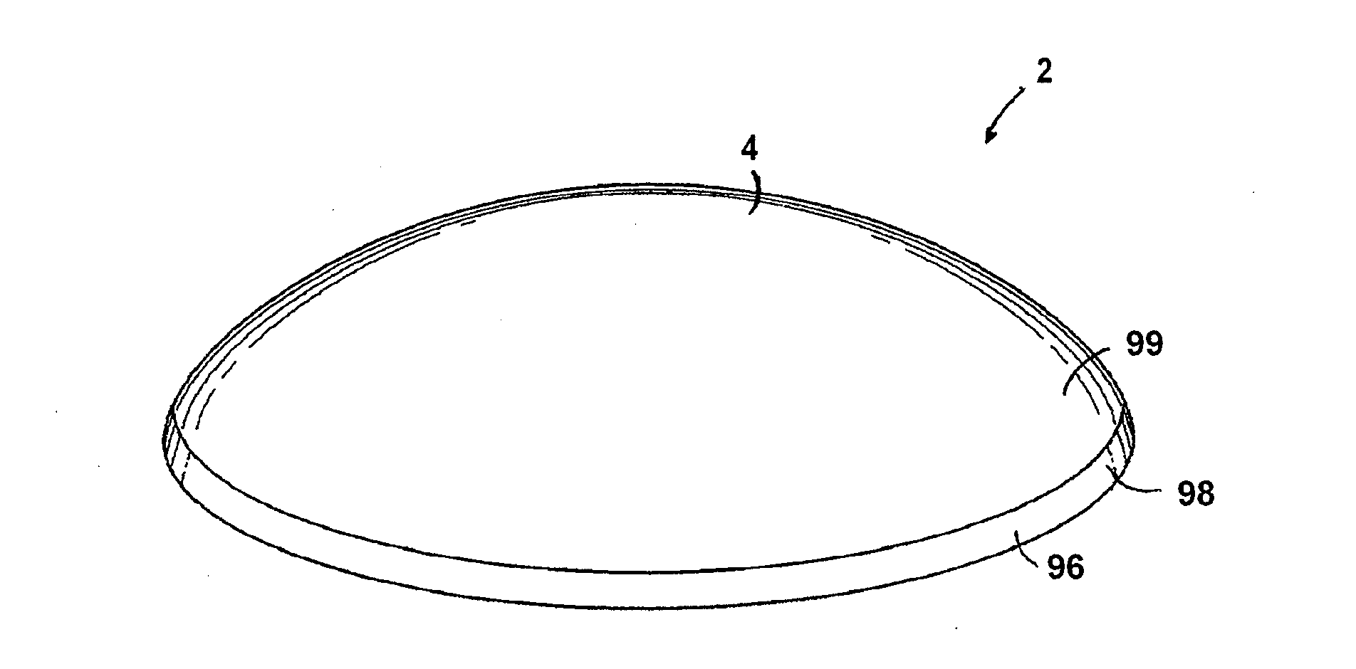
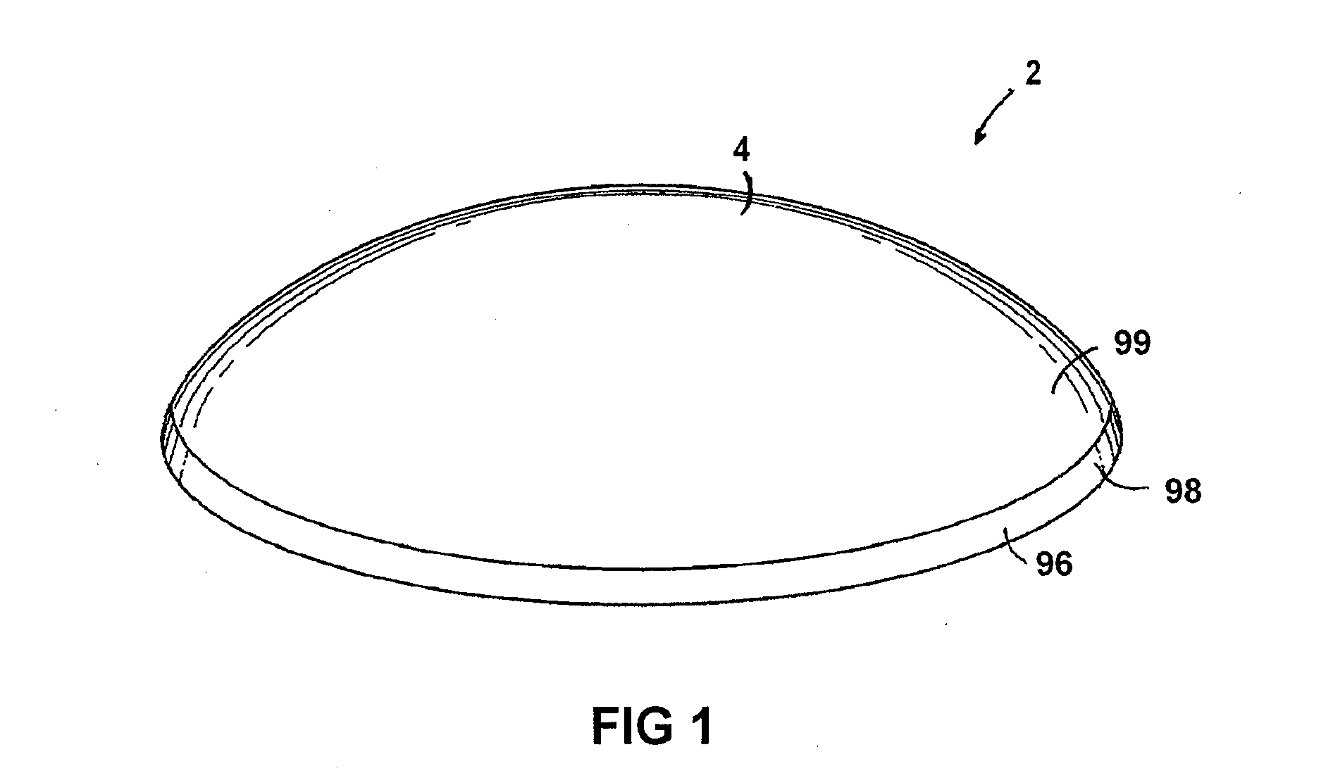
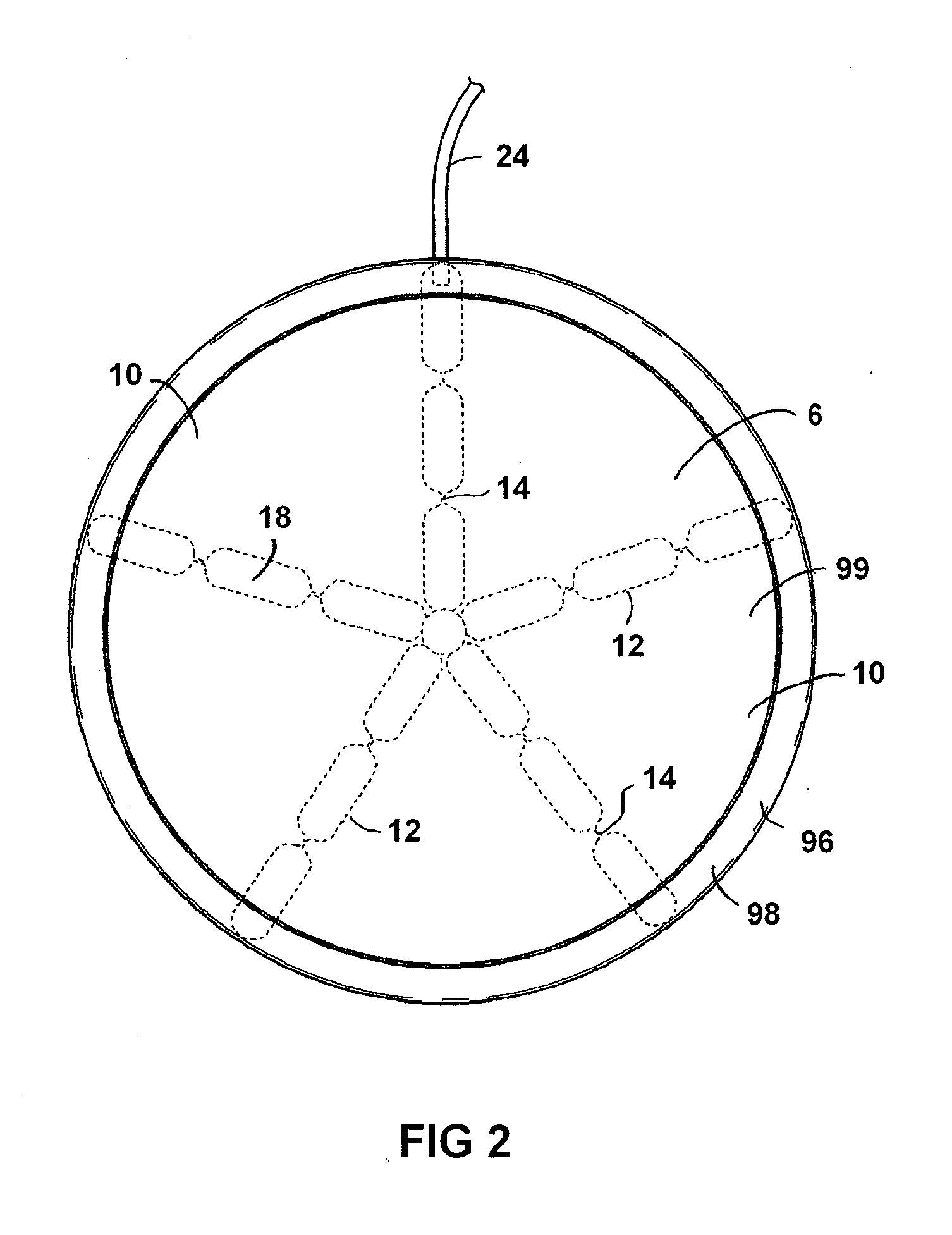
[0047]Referring to FIGS. 1-6, an implantable prosthesis 2 is shown. The prosthesis 2 includes a membrane 4 which may be made formed in any suitable manner. The membrane 4 contains a flowable substance 6 such as silicone gel, saline or any other suitable substance. The flowable substance 6 may also include elements (not shown), such as beads or spheres, which are suspended in the flowable substance 6 without departing from the scope of the invention. Any of the embodiments disclosed herein may incorporate features, structures and materials disclosed in U.S. patent application Ser. No. 11 / 316,215 to Michael Lesh, entitled Tissue Augmentation Device filed Dec. 22, 2005, the disclosure of which is incorporated in its entirety herein by reference.

[0048]The membrane 4 is divided into a number of chambers 10 separated by walls 12. The walls 12 each have one or more orifices 14 which have a size which may be adjusted. Changing the size of the orifices 14 in the walls 12 alters the flow char...


PUM


Abstract

An implantable prosthesis is provided having a membrane which holds a flowable substance. The membrane is separated into a first chamber and a second chamber with the first and second chambers being fluidly coupled via an orifice. The orifice has a size which may be adjusted by the user after implanting the prosthesis into the patient.

Description

CROSS-REFERENCE TO RELATED APPLICATIONS[0001]The present application is a continuation application of U.S. patent application Ser. No. 12 / 024,835 filed Feb. 1, 2008, which is hereby incorporated by reference herein in its entirety.BACKGROUND OF THE INVENTION[0002]The present invention is directed to an implantable prosthesis which may be used anywhere in the body such as the breast.[0003]An implant provides support for the surrounding body tissue and occupies voids created by the removal of tissue to preserve the normal outward appearance and feel of the body. Prosthetic devices have also been used to enhance or augment the appearance of body parts.[0004]Breast prostheses have long been used for breast augmentation and for reconstruction such as following a mastectomy. The prostheses are available in numerous sizes and shapes including teardrop, round and low profile. Usually, breast prostheses are implanted via a small inframammary or pari-aerolar incision into a pocket dissected d...

Claims


Application Information

Patent Timeline
Patent Type & Authority Applications(United States)
IPC IPC(8): A61F2/12
CPCA61F2/12A61F2/0059A61F2/0077A61F2/52A61F2230/0034A61F2230/0093A61F2250/0003A61F2250/0009A61F2250/001A61F2250/0012A61F2250/0013A61F2250/0015A61F2250/0024A61F2250/0025A61F2250/0028A61F2250/0051
Inventor KESTEN, RANDY J.LESH, MICHAEL D.
Owner EVERA MEDICAL
Why Eureka
Try Eureka