Check patentability & draft patents in minutes with Patsnap Eureka AI!

Steam Drawing Device

a drawing device and fiber yarn technology, applied in the direction of other washing machines, liquid/gas/vapor textile treatment, cleaning using liquids, etc., can solve the problems of fiber yarn swaying, damaged yarn surface, and possible touch of yarn structural members, so as to prevent the formation of fuzz and completely cut yarn

Inactive Publication Date: 2014-07-24
MITSUBISHI CHEM CORP
View PDF9 Cites 3 Cited by
  • Summary
  • Abstract
  • Description
  • Claims
  • Application Information

AI Technical Summary

Benefits of technology

The steam drawing apparatus helps prevent yarn from getting stuck in the pressurized section, which can cause problems like broken single fibers, fuzz, and yarn cuts. This results in high-quality yarn that is consistent in quality.

Problems solved by technology

On the other hand, when a pressurized steam drawing apparatus is used, pressurized steam may cause the fiber yarn to sway, and the yarn may touch structural members in the apparatus.
However, when the yarn touches the labyrinth seal section, such contact may cause problems such as damaged yarn surface, broken single fibers, formation of fuzz, or entirely cut yarn.
Such problems may cause further fuzz during flameproofing and carbonization process and may lower the quality of a subsequently obtained carbon fiber.

Method used


Image

  • Steam Drawing Device
  • Steam Drawing Device
  • Steam Drawing Device

Examples


example 1

[0088]Acrylonitrile copolymer made of 98% acrylonitrile and 2% methacrylic acid was dissolved in dimethylformamide to prepare a spinning stock solution with a polymer concentration of 23%. The spinning stock solution was discharged in a 10° C. coagulation bath with an 80% concentration using a spinning nozzle to obtain coagulated fibers. The coagulated fibers were subjected to washing, cool drawing and hot-water drawing, followed by oil treatment and dry-densification. Accordingly, an acrylic yarn was obtained.

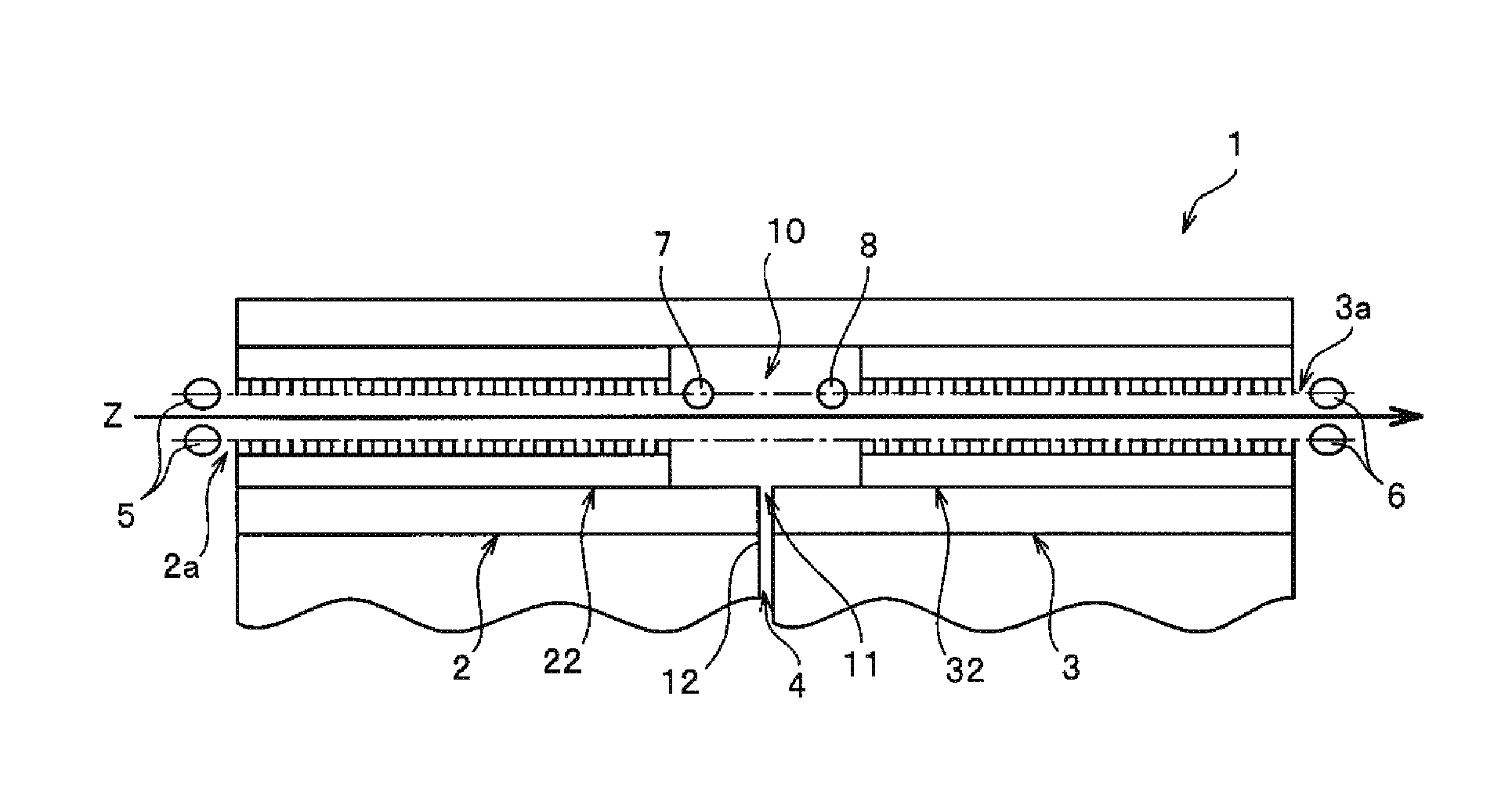
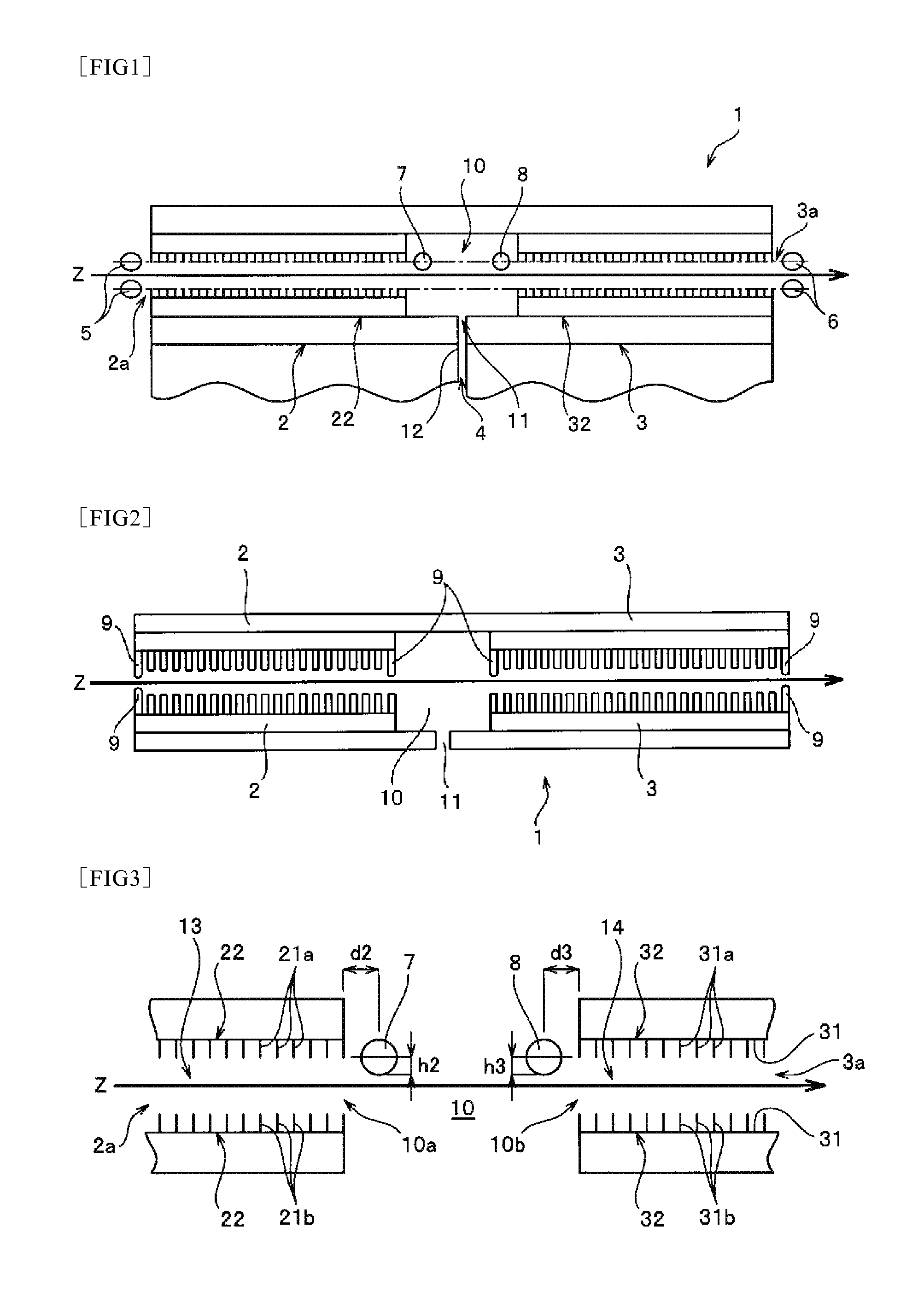
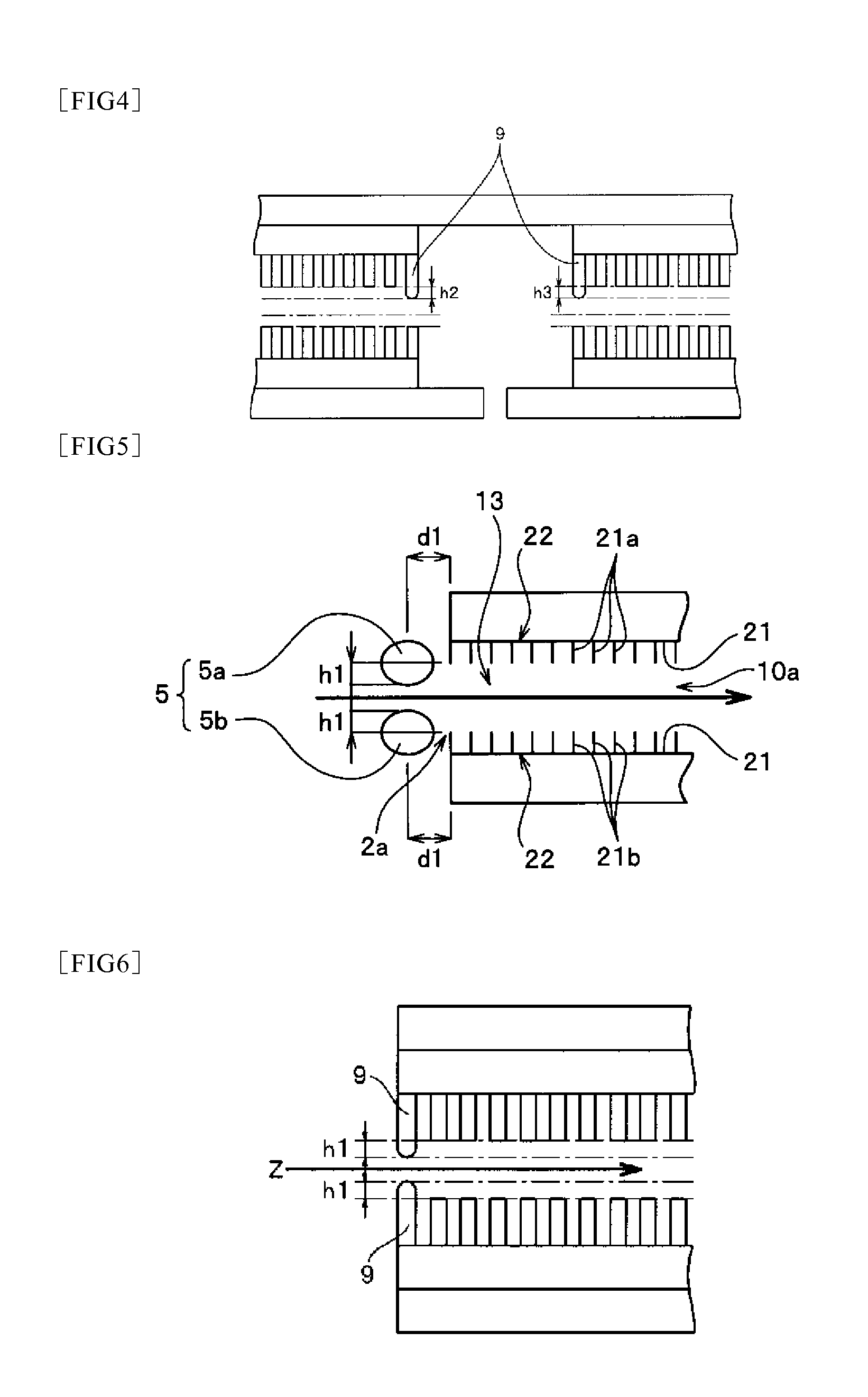
[0089]The obtained acrylic yarn was drawn using a steam drawing apparatus which is provided with a 500-mm-long steam chamber in the yarn running direction into which pressurized steam is introduced along with first and second seal chambers arranged adjacent respectively to the yarn entrance and exit of the steam chamber. Such a steam drawing apparatus is structured as follows:

labyrinth seal is used for seal chambers having multiple plate pieces that extend at right angles towa...

examples [UNK]

Examples 2˜14

[0094]Carbon-fiber precursor yarns were each obtained the same as in Example 1 except that the positions of yarn-position regulating bars were changed as shown in Table 1. The fuzz formations on the obtained precursor yarn were each evaluated and the results are shown in Table 1.

example 15

[0095]Carbon-fiber precursor yarn was obtained the same as in Example 1 except that the plate piece closest to the yarn entrance among plate pieces of the first seal chamber was rounded and set as a third yarn-position regulating bar, the plate piece closest to the yarn exit among plate pieces in the second seal chamber was rounded and set as a fourth yarn-position regulating bar, and each setting was changed as shown in Table 1. The formation of fuzz on the obtained precursor yarn was evaluated and the result is shown in Table 1.

[0096]The third yarn-position regulating bar is arranged in the first seal chamber and the fourth yarn-position regulating bar is arranged in the second seal chamber.


PUM

PropertyMeasurementUnit
distanceaaaaaaaaaa
distanceaaaaaaaaaa
Distanceaaaaaaaaaa

Abstract

A steam drawing apparatus for providing pressurized steam on running yarn to draw the yarn, comprising a steam chamber; first seal chamber adjacent to a yarn entrance of the steam chamber; and second seal chamber adjacent to a yarn exit of the steam chamber, first seal chamber and second seal chamber are each provided with a labyrinth seal section having a plurality of plate pieces, first yarn-position regulating bar is provided to prevent the running yarn from touching the plate pieces, first yarn-position regulating bar extends horizontally intersecting the running direction of the yarn at right angles, and a horizontal plane passing through the point of the first yarn-position regulating bar closest to the yarn is set at least 0.1 mm closer to the yarn than a horizontal plane passing through the tip of the plate piece closest to the yarn.

Description

FIELD OF THE INVENTION[0001]The present invention relates to a steam drawing apparatus for fiber yarn, more specifically, to a steam drawing apparatus capable of consistently drawing precursor fiber yarn for acrylic carbon fiber at a high stretch ratio.DESCRIPTION OF BACKGROUND ART[0002]Conventional drawing techniques using pressurized steam have been known in the fiber manufacturing industry. When pressurized steam is used, a higher temperature is obtained than when using hot water under atmospheric conditions, and the presence of water leads to a plasticizing effect on the cellulose polymer, thus resulting in drawing at a high stretch ratio.[0003]On the other hand, when a pressurized steam drawing apparatus is used, pressurized steam may cause the fiber yarn to sway, and the yarn may touch structural members in the apparatus. Especially in the labyrinth seal section of the steam drawing apparatus, in order to improve the sealing effects of steam, it is preferred to employ a labyri...

Claims


Application Information

Patent Timeline
Patent Type & Authority Applications(United States)
IPC IPC(8): D02J1/22D06B23/16
CPCD06B23/16D02J1/222D02J13/001D02J13/006D06B3/045D06B23/18
Inventor TADA, AKISHIGEOOKI, ISAOMIZUTORI, YUKIHIRO
Owner MITSUBISHI CHEM CORP
Features
  • R&D
  • Intellectual Property
  • Life Sciences
  • Materials
  • Tech Scout
  • Unparalleled Data Quality
  • Higher Quality Content
  • 60% Fewer Hallucinations
Learn More