Cable retractor

a retractor and cable technology, applied in the direction of arrangement using a take-up reel/drum, etc., can solve the problems of unfavorable use, safety hazards, and suffer from slip rings on the cable retractor, and achieve the effect of paying out and increasing the amount of cabl

Inactive Publication Date: 2014-08-14
HAWORTH SPA
View PDF45 Cites 8 Cited by
  • Summary
  • Abstract
  • Description
  • Claims
  • Application Information

AI Technical Summary

Benefits of technology

[0004]The present invention provides a cable retractor for use in a variety of applications, including in compact spaces, that is capable of extending and retracting a length of cable. In one embodiment, the cable retractor includes a housing forming an internal chamber and first and second drums within the chamber for winding of the cable. The first drum may include a stationary outer surface, and the second drum may be formed by a plurality of rollers mounted on a rotatable frame. The rollers may orbit about the first drum upon rotation of the frame, with each of the rollers also rotating about its own roller axis. The first and second drums may be sized to enable wrapping of the cable both side-by-side and in multiple layers about at least one of the first drum and the second drum. The ability to wrap the cable in multiple side-by-side wraps and in multiple layers on one or both of the first and second drums enables the cable retractor of the present invention to pay out a larger amount of cable than many previous styles and arrangements of cable retractors.
[0006]In another embodiment, the cable retractor includes structure to urge the rollers to rotate with respect to the frame as the frame rotates. For example, the housing may include a track, and a portion of each of rollers may engage the track during rotation of the frame, the engagement urging the rollers to rotate about the roller axes. The portion of the rollers may be frictionally engaged with the track, and capable of slipping with respect to the track to provide smooth extension and retraction of the cable even as multiple layers of cable are wound about the first and second drums.

Problems solved by technology

Although relatively easy to use, these slip ring style cable retractors suffer from a number of disadvantages.
First, they can be a safety hazard when used in environments where there is a possibility of a spark from the slip rings setting off an explosion, or the possibility of shorting by the slip rings coming into contact with moisture.
In addition, they are not conducive to use with cables that require a large number of electrical conductors, such as HDMI or VGA cables because it can be highly complex to create the numerous connections with slip rings.
They also cannot be used with cables that require continuity, such as fiber optics.
This style of retractor enables extension and retraction of cable without the use of slip rings, but generally suffers in that they allow only a small payout of cable for a relatively large housing.
The Meson device allows only side-by-side winding of the cable on the drums, which limits the amount of cable that can be retracted and / or requires a very large unit.
The Liao device allows for overlapping layers of the cable, but does not enable side-by-side wrapping of the cable.
Further problems are caused by the fact that both of these devices require a tight bend in the cable at the location where the cable exits the central drum.

Method used


Image

  • Cable retractor
  • Cable retractor
  • Cable retractor

Examples


Embodiment Construction

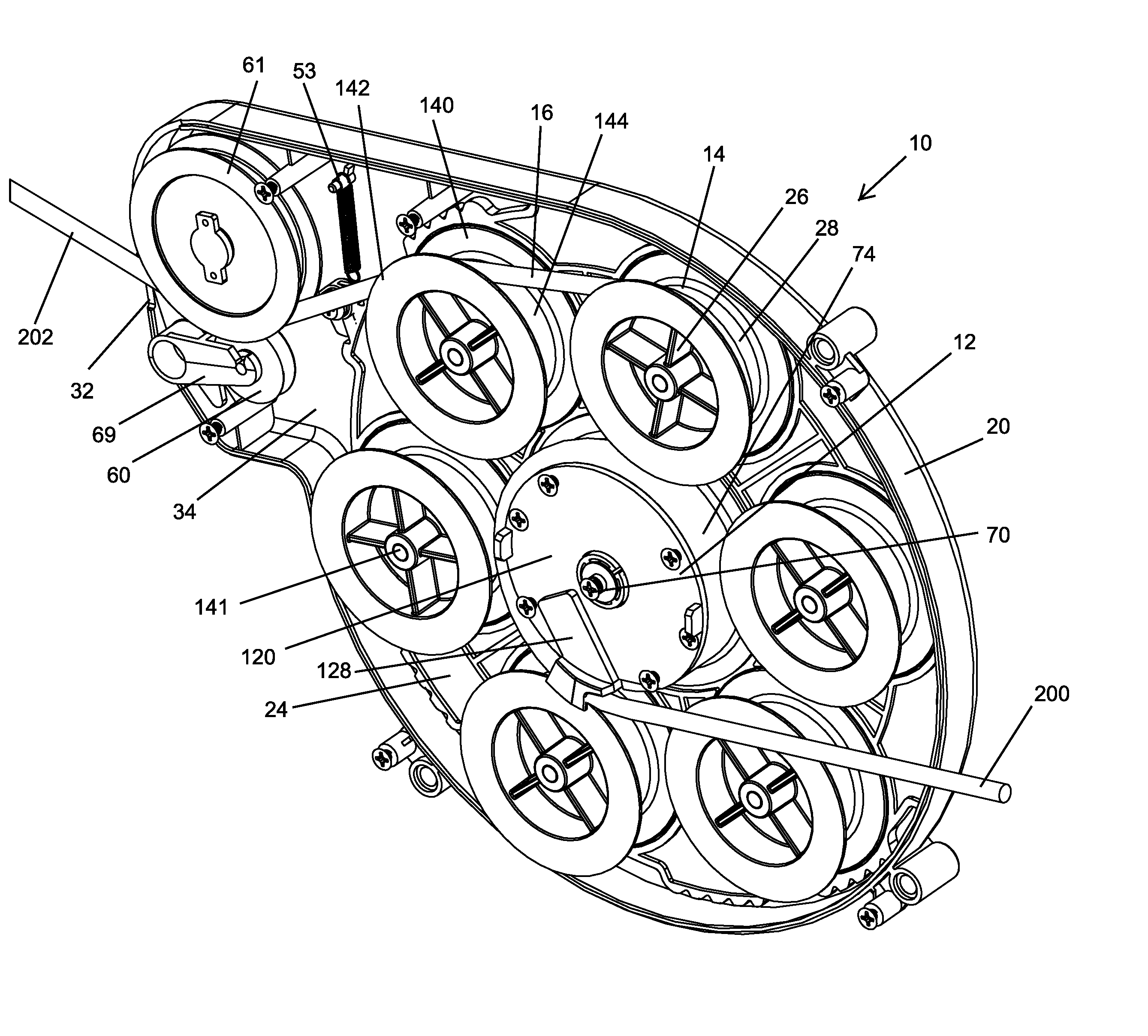
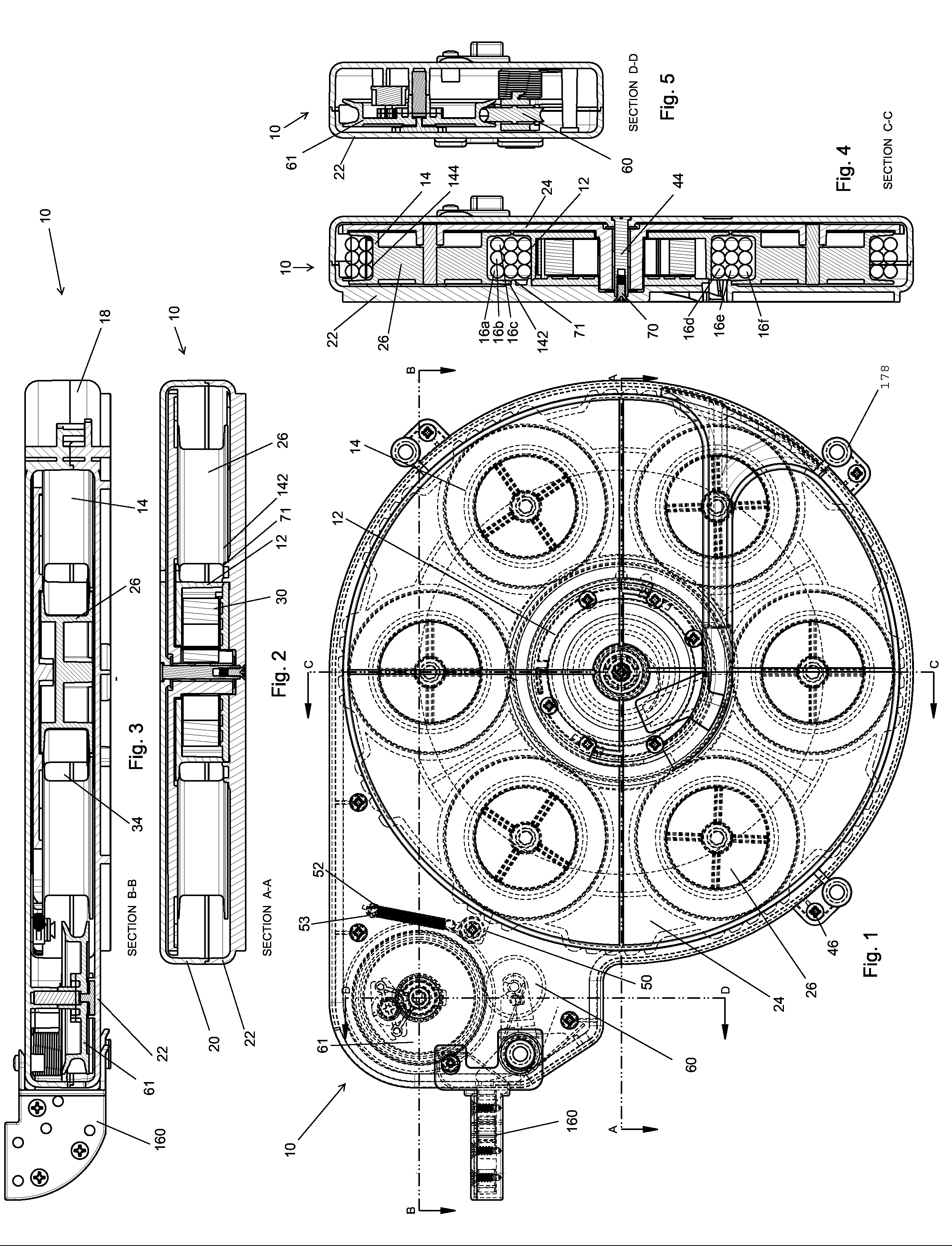
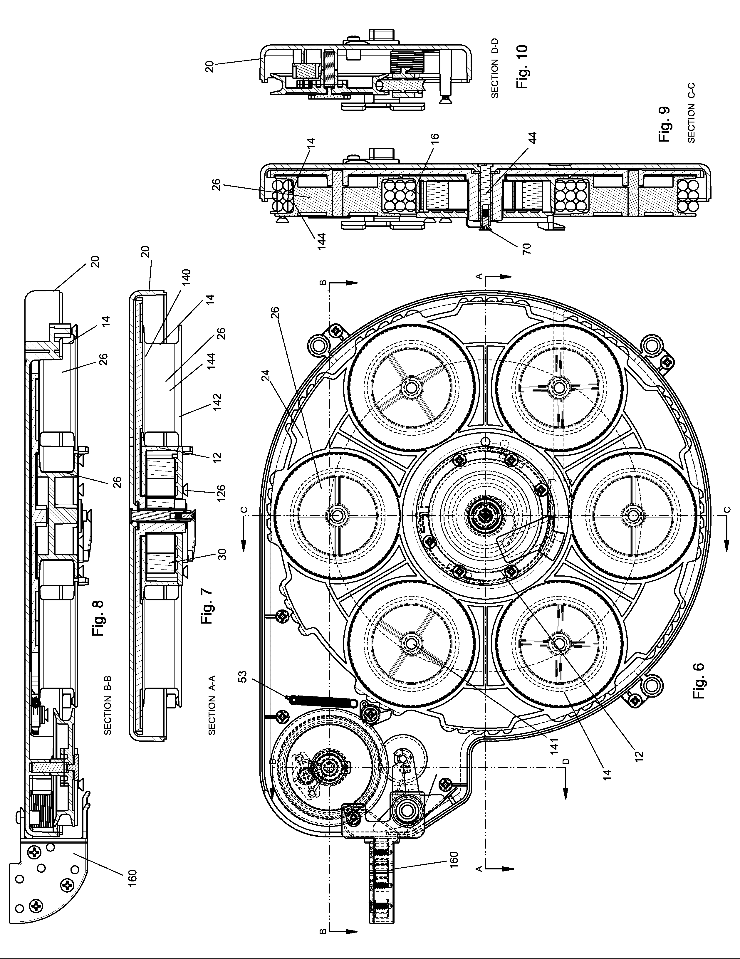
[0039]A cable retractor according to the current embodiments of the present invention is shown in the Figs. and generally designated 10.

[0040]I. Overview

[0041]In general, the cable retractor includes first 12 and second 14 drums about which a cable 16 can be coiled and uncoiled. The drums 12, 14 may be mounted within a housing 18 having a main housing body 20 and a housing cover 22 that combine to form an enclosure. The first drum 12 is stationary, and the second drum 14 is supported on a rotating frame 24 to revolve about the first drum 12. The frame 24 may be connected to a spring 30 that biases the frame to rotate in one direction when the spring is loaded. The second drum 14 is formed from a plurality of individual rollers 26 can each rotate with respect to the frame 24 as the rollers 26 revolve about the first drum 12. One of the rollers 28 forms a guide roller for transferring the cable 16 from the second drum 14 to the first drum 12. As the frame 24 rotates in the one directi...


PUM


Abstract

A cable retractor for use in a variety of applications includes a housing forming an internal chamber, and first and second drums within the chamber for winding of the cable. The first drum may include a stationary outer surface, and the second drum may be formed by a plurality of rollers mounted on a rotatable frame. The rollers may orbit about the first drum upon rotation of said frame, with each of the rollers also rotating about its own roller axis. The first and second drums may be sized to enable wrapping of the cable both side-by-side and in multiple layers about at least one of the first drum and the second drum. The cable retractor may include structure to urge the rollers to rotate with respect to the frame as the frame rotates. For example, a portion of the rollers may be frictionally engaged with a track, and capable of slipping with respect to the track to provide smooth extension and retraction of the cable even as multiple layers of cable are wound about the first and second drums.

Description

BACKGROUND OF THE INVENTION[0001]The present invention relates to cable retractors, and more particularly to a device for extending and retracting a first end of a length of cable as the second end of the length of cable is held stationary.[0002]One common type of cable retractor, known as a “slip ring” style cable retractor, includes a housing and a drum positioned within the housing. The drum is connected to a spring for urging the drum to rotate, and the cable is wound around the drum as the drum rotates. Slip rings are used to convey the electrical energy from the moving portion of the cable retractor, generally a portion of the drum, to a stationary portion of the cable retractor. Although relatively easy to use, these slip ring style cable retractors suffer from a number of disadvantages. First, they can be a safety hazard when used in environments where there is a possibility of a spark from the slip rings setting off an explosion, or the possibility of shorting by the slip r...

Claims


Application Information

Patent Timeline
Patent Type & Authority Applications(United States)
IPC IPC(8): B65H75/48B65H75/44
CPCB65H75/48B65H75/4436B65H75/4418B65H75/4402B65H75/4434B65H75/4449B65H2701/34H02G11/02
Inventor WILSON, HAROLD R.
Owner HAWORTH SPA
Why Eureka
Try Eureka