

Radiation imaging apparatus, radiation inspection apparatus, method for correcting signal, and computer-readable storage medium
a radiation inspection and imaging apparatus technology, applied in the field of radiation imaging apparatus, radiation inspection apparatus, method for correcting signals, and computer-readable storage media, can solve the problems of affecting inspection or diagnosis, loss of continuity between adjacent signals, etc., and achieve the effect of improving the quality of an imag
- Summary
- Abstract
- Description
- Claims
- Application Information
AI Technical Summary
Benefits of technology
Problems solved by technology
Method used
Image

Examples
first embodiment
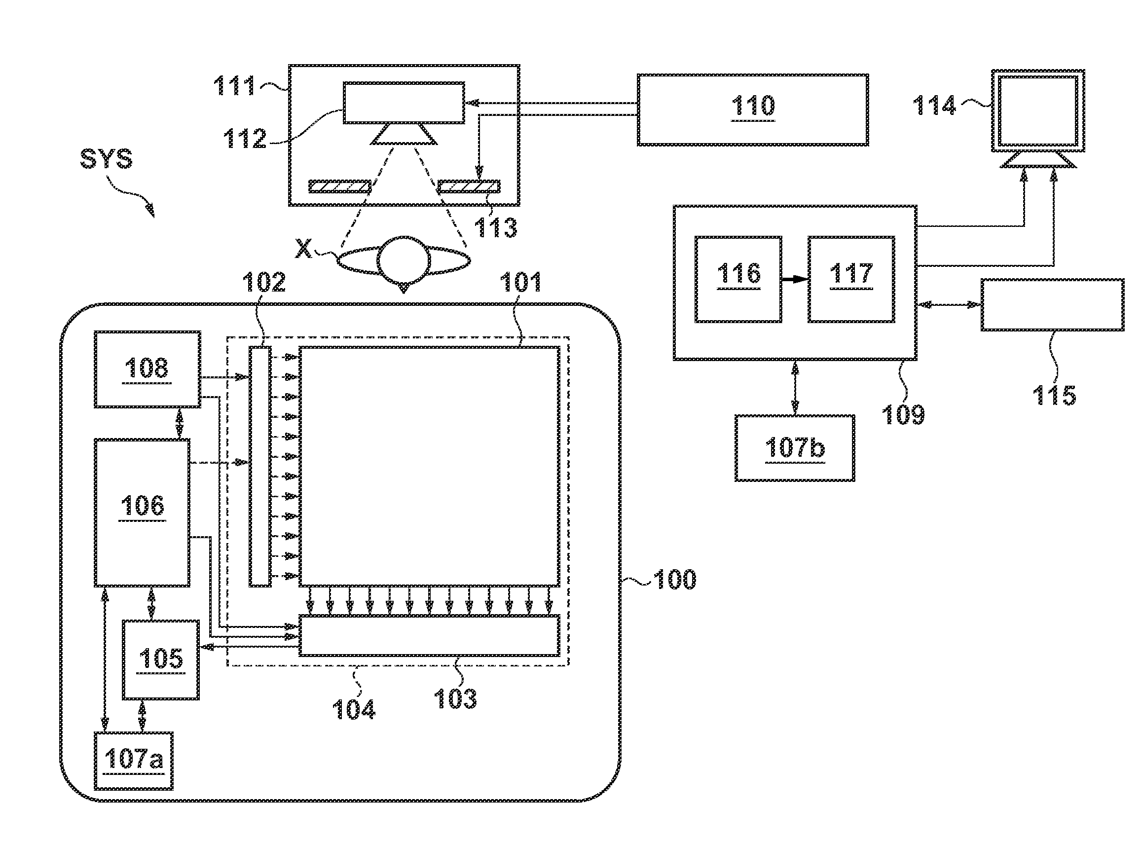
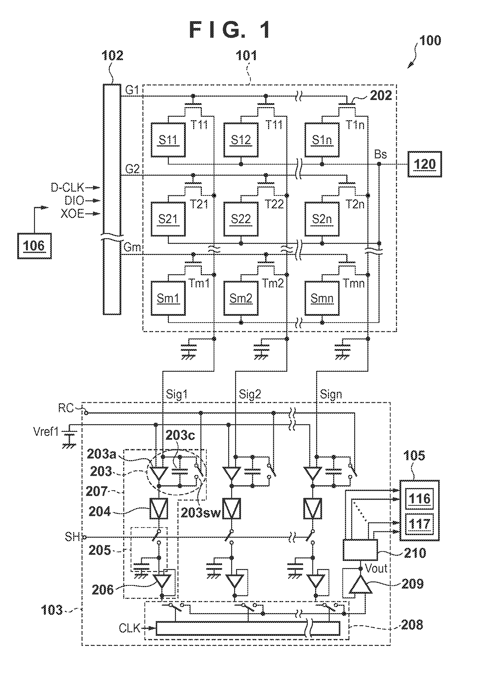
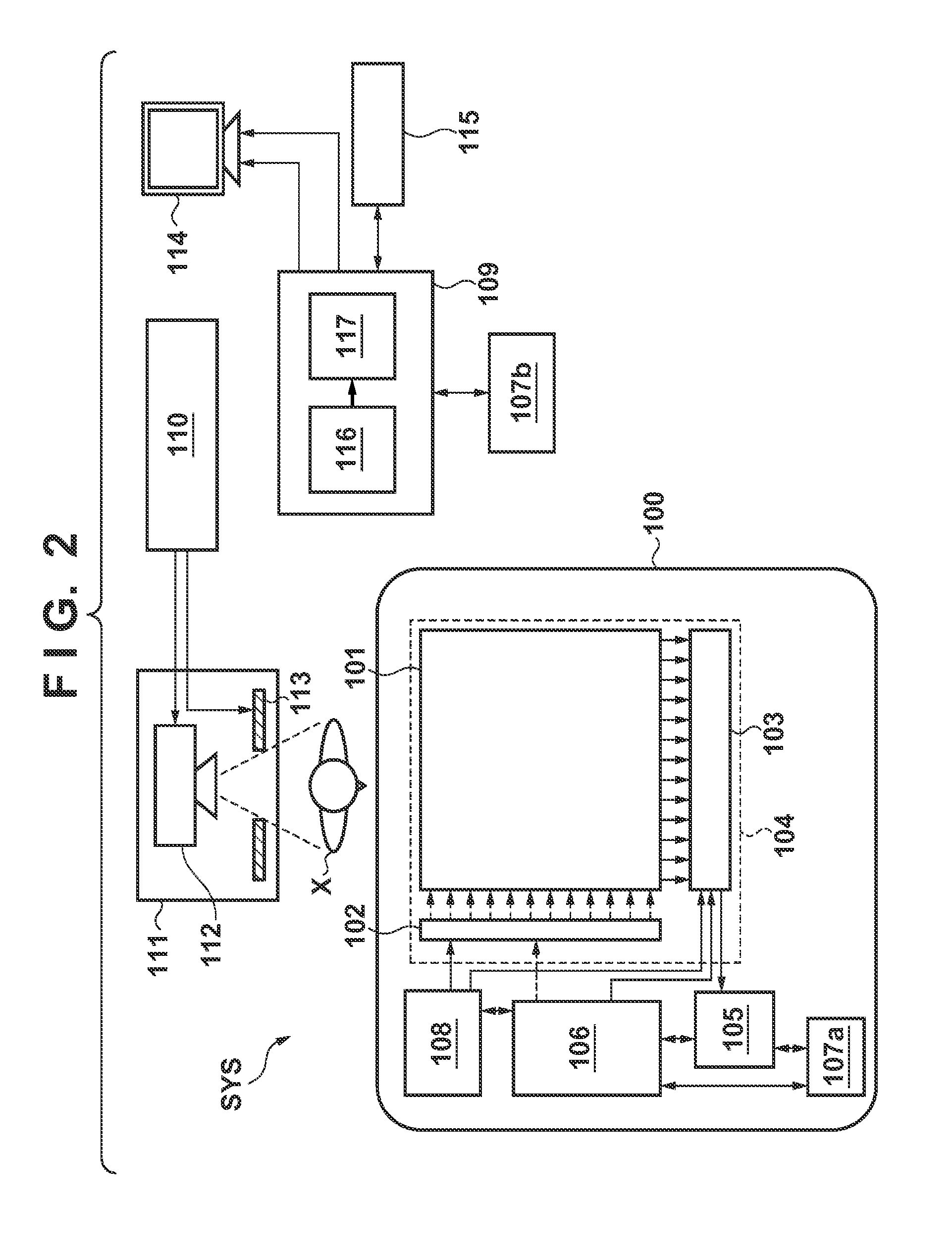
[0030]First, the operation sequence of a radiation imaging apparatus 100 will be described. As exemplified in FIG. 3, a control unit 106 controls a driving unit 102 to mainly perform a reset operation, standby operation, and readout operation. In the reset operation, for example, switching elements T can be turned on sequentially for the respective rows in accordance with a control signal from the driving unit 102, and respective pixels can be cyclically reset for every row. In the reset operation, a signal line Sig is fixed to a reference potential Vref1, and when the switching element T is turned on, a conversion element S is initialized.
[0031]In the first embodiment, the reset operation can be performed by alternately repeating resetting of pixels arranged on odd-numbered rows G1, G3, G5, . . . , Gm−1 in a sensor unit 101, and resetting of pixels arranged on even-numbered rows G2, G4, G6, . . . , Gm. According to this reset method, for example, when large noise is mixed in one si...
second embodiment
[0051]The second embodiment will be described with reference to FIG. 7. The second embodiment will examine a case in which a radiation imaging apparatus 100 is operated according to the same sequence as that in the first embodiment. However, the second embodiment is different from the first embodiment in the method for correcting a signal. FIG. 7 shows a plot similar to that in the first embodiment (FIG. 4B). In the second embodiment, a determination unit 116 determines which of a saturated signal and non-saturated signal is a signal DX obtained by a readout operation H1, and specifies a portion at which these two signals are mixed. At this time, a difference Δdx (absolute value) between saturated and non-saturated signals obtained from two adjacent pixels can be calculated.
[0052]Then, a signal obtained by a readout operation H2 can be analyzed. More specifically, a difference Δdf (absolute value) between a signal output in the readout operation H2 from a pixel which has output a sa...
third embodiment
[0053]The third embodiment will be described with reference to FIGS. 8, 9A, and 9B. The third embodiment is different from the first or second embodiment in that respective pixels P are cyclically reset for every two or more rows, as exemplified in FIG. 8. A case in which the respective pixels P are cyclically reset for every four rows will be exemplified. This reset method improves the responsiveness of radiation detection of a detection unit 120 because the current amount on a bias line Bs increases. Also, this reset method can reduce shading of an image signal because the time difference in standby operation between adjacent rows is decreased.
[0054]Even when a radiation imaging apparatus 100 is operated by this reset method, a striped artifact may appear in a radiation image obtained by the radiation imaging apparatus 100. More specifically, when the respective pixels P are cyclically reset for every four rows, a noise component mixed in a signal from a row of a smallest row G nu...
PUM
 Abstract
Description
Claims
Application Information