

Dual head connector
a head connector and dual technology, applied in the field of dental implants and other orthodontic appliances, can solve the problems of increased risk of damage, complicated treatment with braces, and inability to shorten, so as to facilitate molar conta
- Summary
- Abstract
- Description
- Claims
- Application Information
AI Technical Summary
Benefits of technology
Problems solved by technology
Method used
Image

Examples
Embodiment Construction
[0072]The disclosure describes a bite plate having a socket therein, preferably having many of the characteristics of the special prior art bite plates described in US2008227046, US2008227047, US2010055634, US20120322018, 61 / 624,242, 61 / 615,480 and 61 / 673,236 and intended to be used with intra-oral or extra-oral vibratory or other treatment modality sources, as described in the preceding applications for patent, each incorporated by reference in their entireties.
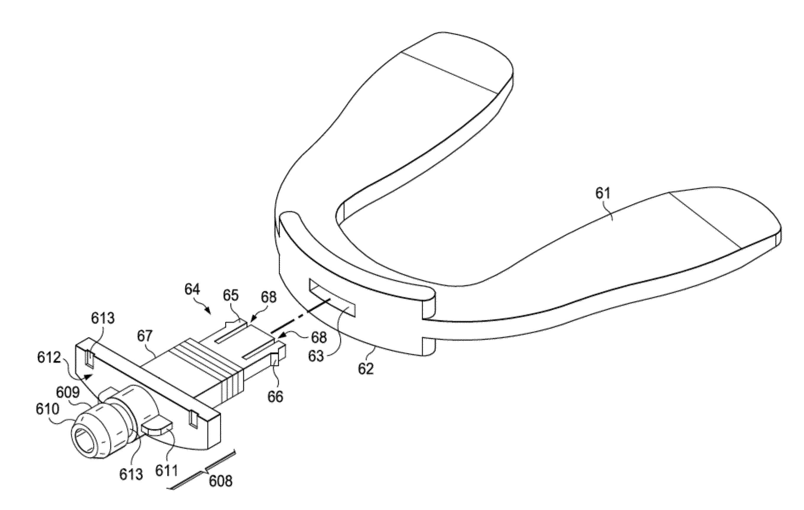
[0073]Also included is a dual head connector, for connecting the socketed bite plate to a socketed driver. Preferably, the driver end has the same dimensions as the existing bite plate, and can therefore be used with the existing drivers that are already on the market. The other end can be any suitable connector, including snap fitting connectors, cantilevered snap fits, threadable screw fits, luer lock-style fits, friction fits, and the like. The bite plate or other appliance will of course be modified to provide a socket f...
PUM
 Abstract
Description
Claims
Application Information