Disintegrating device

a technology of disintegrating devices and disintegrating parts, which is applied in the direction of cocoa, solid separation, grading, etc., can solve the problems of increasing maintenance effort, and achieve the effect of reducing the amount of manual power and facilitating the operation of the disintegrating devi

Inactive Publication Date: 2015-08-06
DOPPSTADT FAMILIENHOLDING GMBH
View PDF2 Cites 14 Cited by
  • Summary
  • Abstract
  • Description
  • Claims
  • Application Information

AI Technical Summary

Benefits of technology

[0014]It is also an advantage when the entire screening device is provided at the horizontally orientated comb carrier shaft, pivotable preferably along with the joint. Thus, of course, the screening device can be positioned or arranged depending on the material to be disintegrated and screened in differing distance from the disintegrating roller with the disintegrating tools. It is another advantage here when the comb carrier is arranged at the frame releasably/fixedly.
[0015]The pivot unit for swinging out the entire assembly is provided preferably as hydraulic cylinder swinging out or in the common assembly via a pivot axis orientated vertically seen in mounting direction out of the wall plane of the machine frame. This increases further the ease of operating the disintegrating device according to the invention. By providing a hydraulic cylinder the manual power to be applied is reduced considerably. Of course, instead of a hydraulic cylinder also a linear motor or an electro-mechanic adjusting unit can be provided. However, as usually hydraulic drives are present in the discussed disintegrating devices, of course, preferably also here a hydraulic cylinder is employed.
[0016]The hydraulic cylinder and/or the pivot unit are provided on at ...

Problems solved by technology

This increases the...

Method used


Image

  • Disintegrating device
  • Disintegrating device
  • Disintegrating device

Examples


Embodiment Construction

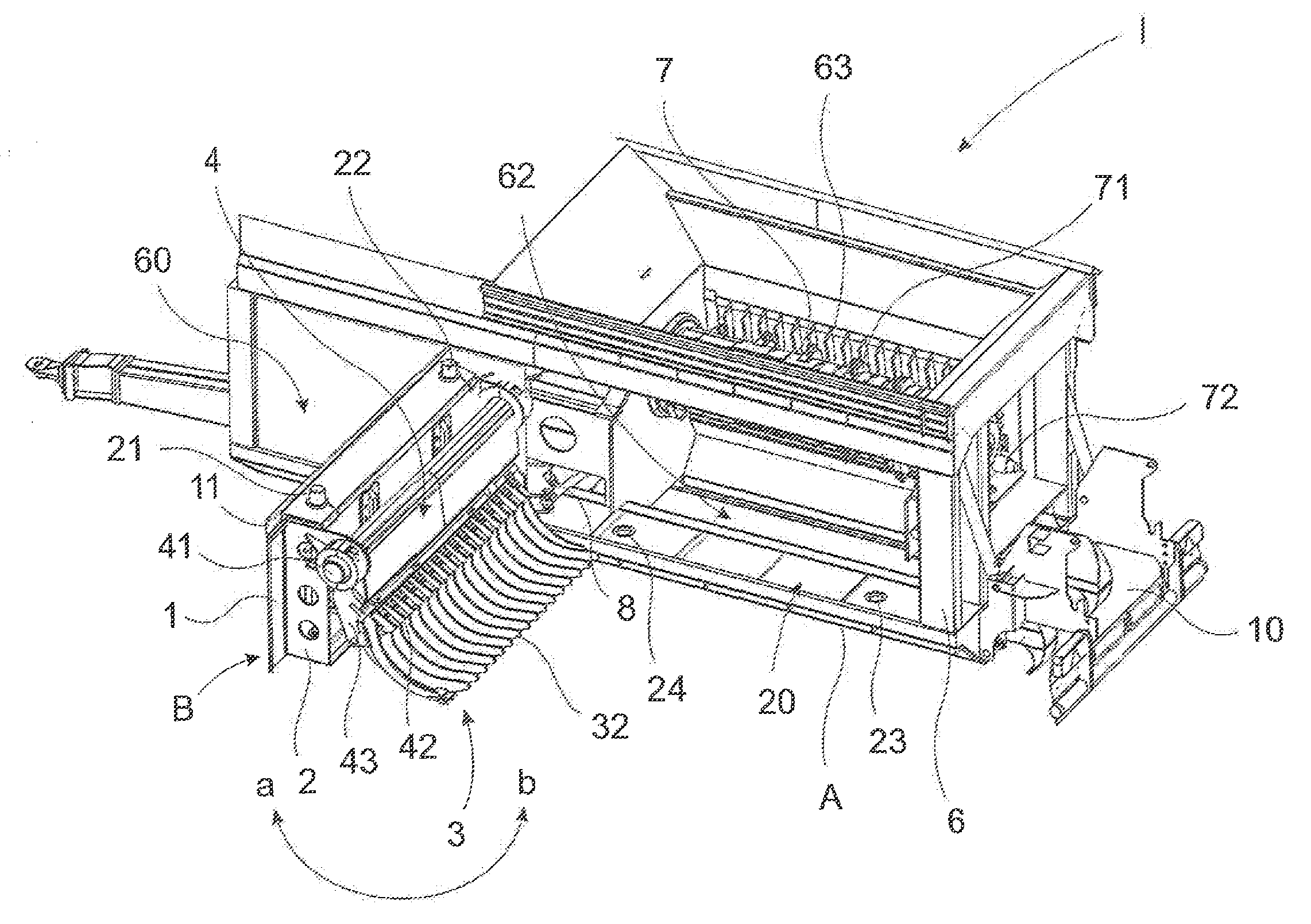
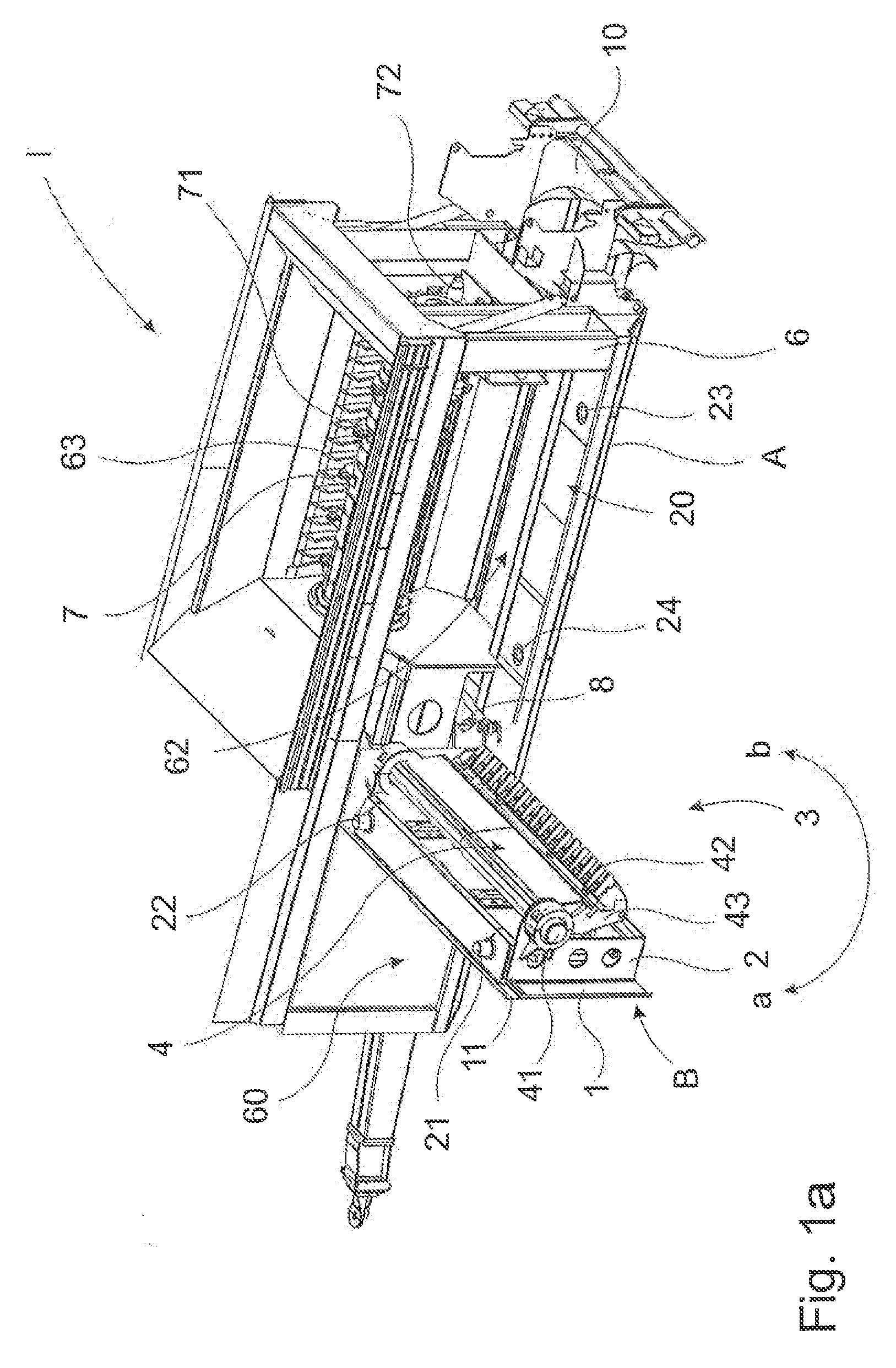
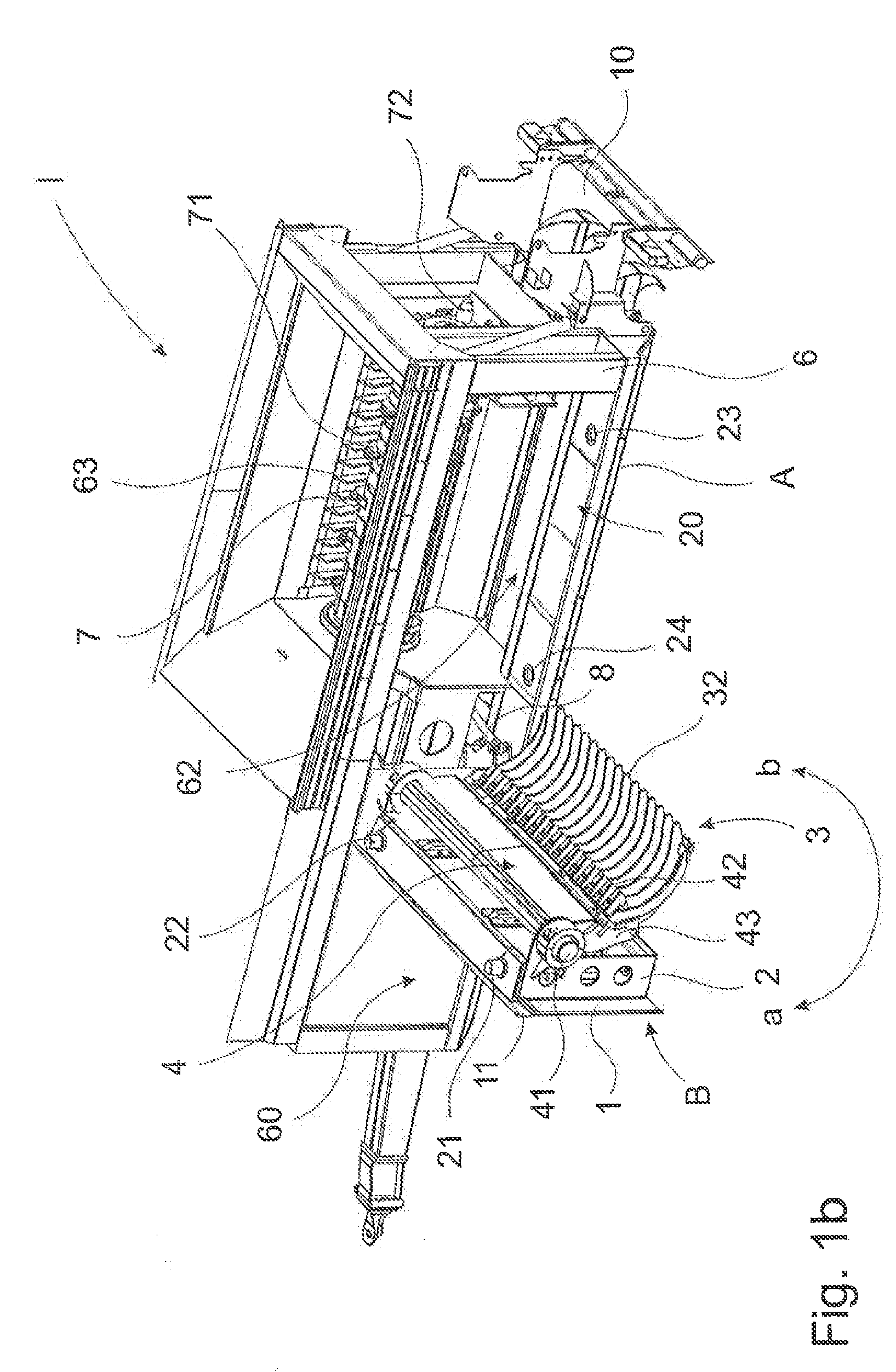
[0028]FIG. 1a shows a disintegrating device I according to the invention without screening device with swung-out assembly B. The disintegrating device I and the assembly B are indicated schematically by one arrow each. The machine housing 6 is installed on an installation surface A on the floor and / or an installation plane not indicated in detail. The installation surface A is here the bottom end of the machine housing 6 seen in installation direction. The common assembly B comprises a part of the wall 61 of the machine housing 6 and / or the wall plane 60. The part of the machine wall that cannot be swung out is referred to by wall plane 60. The pivotable assembly B comprises in the representation of FIG. 1a frame 2 inserted in a part of the wall 61 via a guide 11. A comb carrier 4 where the counter blades 42 are arranged is arranged at the frame 2. Furthermore, a comb carrier shaft 41 is indicated the comb carrier being pivotable thereon. Several counter blades 42 form a counter com...


PUM


Abstract

The invention relates to a disintegrating device, comprising a machine housing, which can be installed on an installation plane or an installation surface, and at least one disintegrating roller. The disintegrating rollers is rotatably supported in the machine housing and has at least one disintegrating tool arranged thereon, at least one counter blade, which interacts with the disintegrating tool, and at least one comb carrier on at least one wall of the machine frame extending parallel to the axis of rotation of the disintegrating roller. The invention is characterized in that at least part of the wall of the machine housing forms a common, in particular pivotable assembly together with the comb carrier.

Description

[0001]The invention relates to a disintegrating device, consisting of at least one disintegrating roller supported rotatably in a machine housing with at least one disintegrating tool arranged thereon with at least one counter blade interacting with the disintegrating tool, and with at least one comb carrier provided at least at one wall of the machine frame extending parallel to the rotational axis of the disintegrating roller.BACKGROUND OF THE INVENTION[0002]Disintegrating devices of this kind are sufficiently known in the state of the art, for example from the citations DE 83 31 826 U1, DE 20 2008 006 802 U1, and WO 2010 / 032 037 A1. The rather poor accessibility of the disintegrating roller is a problem during cleaning and maintaining, in particular also during a necessary change of disintegrating tools. The service person often has to bend from above into the housing and turn the roller accordingly in order to reach the disintegrating tools. If tools and / or counter blades are wo...

Claims


Application Information

Patent Timeline
IPC IPC(8): B02C18/14B02C18/20
CPCB02C18/145B02C18/20B02C2018/188B02C2018/162
Inventor DOPPSTADT, JOHANNBERGER, HORST
Owner DOPPSTADT FAMILIENHOLDING GMBH
Why Eureka
Try Eureka