Ankle float buoy

a floatation device and ankle technology, applied in swimming aids, gymnastic exercise, swimming, etc., can solve the problems of increased drag that would need to be overcome, user discomfort and tiring, and cannot simply stop kicking, so as to improve the fit of the swimmer's anatomy

Active Publication Date: 2015-10-08
TYR SPORT INC
View PDF5 Cites 16 Cited by
  • Summary
  • Abstract
  • Description
  • Claims
  • Application Information

AI Technical Summary

Benefits of technology

[0009]In other embodiments, the ankle openings may be formed in a convex configuration, such that the front and rear openings are wider than a segment of the ankle openings located between the front and rear openings. In particular, this convex configuration may be achieved readily when the buoy is formed from a compression molded foam. One benefit of the convex shape may be that the narrower portion between the rear and front openings may assist in securing the buoy to the swimmer as the portion of the ankle between the swimmer's foot and calf region is generally narrower, thereby allowing the convex formation to better fit to the swimmer's anatomy.

Problems solved by technology

However, one cannot simply stop kicking, as the legs would sink in the water causing an increased amount of drag that would need to be overcome.
This closing exertion, however, can be uncomfortable and tiring for the user and still allows for a certain degree of kicking being performed by the swimmer.
However, these straps can be cumbersome and difficult to attach and remove.
If the swimmer lacks the necessary core strength, the swimmer may break form.
As such, if one is desiring to increase the strength and proficiency of their core, this device is not ideal.

Method used


Image

  • Ankle float buoy
  • Ankle float buoy
  • Ankle float buoy

Examples


Embodiment Construction

[0021]The detailed description set forth below is intended as a description of the presently preferred embodiment of the invention, and is not intended to represent the only form in which the present invention may be constructed or utilized. The description sets forth the functions and sequences of steps for constructing and operating the invention. It is to be understood, however, that the same or equivalent functions and sequences may be accomplished by different embodiments and that they are also intended to be encompassed within the scope of the invention.

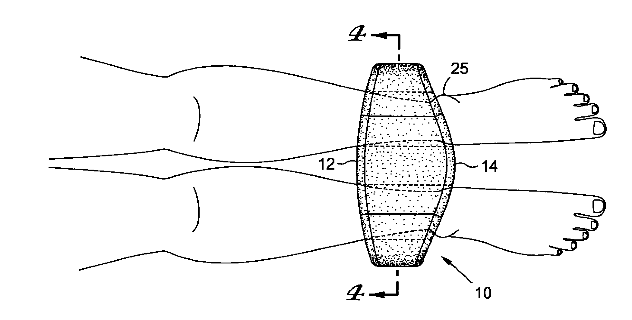
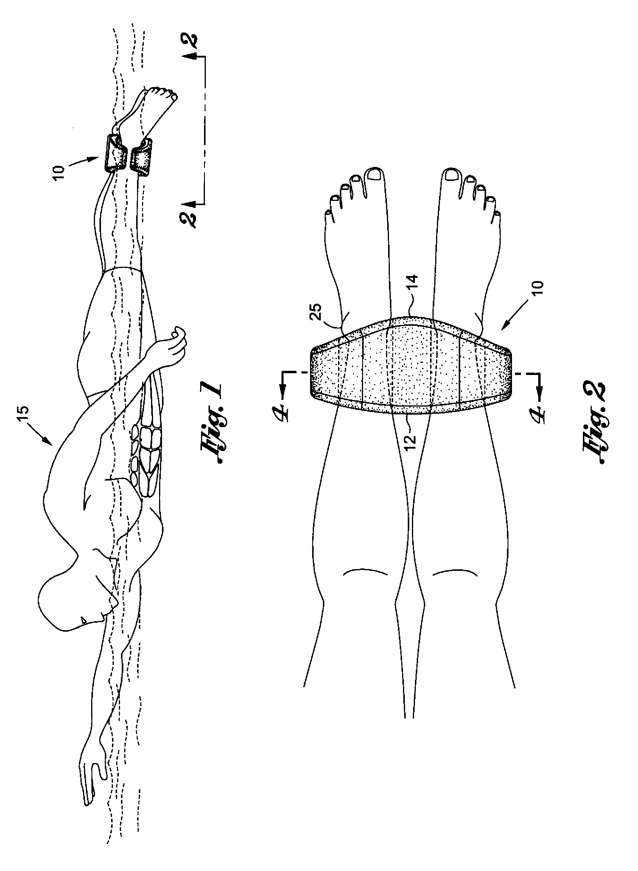
[0022]As shown in FIG. 1, an ankle float buoy 10 is attached to the ankle region of a swimmer 15. This configuration allows the swimmer 15 to isolate and train their arms, shoulders, and core region by focusing on the arm stroke. The buoy 10 may formed of a buoyant, resilient material and is configured to be easily attachable to the ankle region 25 of the swimmer 15. By locating the buoy 10 on the ankles 25, the buoyant force p...


PUM


Abstract

A unitary ankle float buoy for immobilizing the legs during swim training. The buoy is formed of a central portion connecting a top wall and a lower wall and a pair of ankle openings disposed on each side of the central portion. The ankle float buoy is designed and configured to be worn upon both ankles of a swimmer below the calf and above the foot.

Description

CROSS-REFERENCE TO RELATED APPLICATIONS[0001]Not ApplicableSTATEMENT RE: FEDERALLY SPONSORED RESEARCH / DEVELOPMENT[0002]Not ApplicableBACKGROUND[0003]The present disclosure relates generally to an ankle floatation device, and more particularly to a swim training device that maintains a swimmer's legs in a fixed position to focus on the swimmer's core and shoulder training while swimming.[0004]Typically, swimming utilizes an arm stroke and kicking of the legs to propel the swimmer through water. While the arm stroke generally provides the majority of thrust, strong kicking can often compensate for a weak arm stroke. In order to overcome this compensating ability, it is often desired to remove the legs from the stroke to focus on the core and arm muscles to improve the arm stroke. However, one cannot simply stop kicking, as the legs would sink in the water causing an increased amount of drag that would need to be overcome. Additionally, paraplegic swimmers, or others with inabilities t...

Claims


Application Information

Patent Timeline
Patent Type & Authority Applications(United States)
IPC IPC(8): A63B69/12
CPCA63B69/12A63B69/14A63B31/12A63B2225/605A63B31/00A63B23/02A63B23/035
Inventor DILORENZO, MATTHEW V.BAYER, PHILIP M.SOLA, KYLE D.WANG, YANG
Owner TYR SPORT INC
Why Eureka
Try Eureka