

Pixel array
a technology of pixels and arrays, applied in the field of pixels arrays, can solve the problems of limited resolution of pixels displayed by the display panel, and achieve the effect of good resolution and brightness
- Summary
- Abstract
- Description
- Claims
- Application Information
AI Technical Summary
Benefits of technology
Problems solved by technology
Method used
Image

Examples
first embodiment
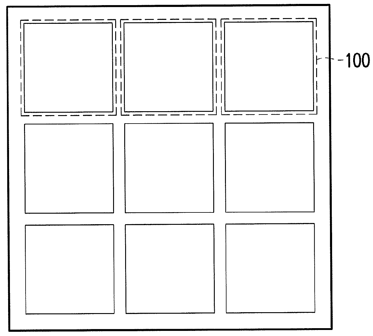
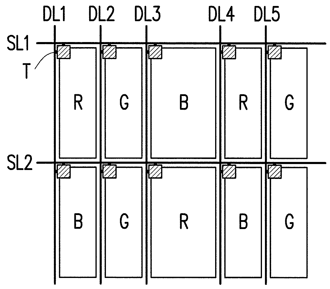
[0026]FIG. 1 is a top schematic of a pixel array according to some embodiments of the invention. FIG. 2 is a top schematic of a repeating unit of a pixel array according to the invention. Referring to FIG. 1 and FIG. 2, a pixel array 1000 includes a plurality of repeating units 100. For ease of explanation, only one repeating unit 100 is illustrated in FIG. 2. However, those having ordinary skill in the art should understand that, the pixel array 1000 is in actuality an array (as shown in FIG. 1) forming by a plurality of repeating units 100. The repeating unit 100 of the present embodiment includes ten sub-pixels that are respectively three first color sub-pixels R, four second color sub-pixels G, and three third color sub-pixels B. Each of the first color sub-pixels R, the second color sub-pixels G, and the third color sub-pixels B independently includes a scan line, a data line, and a driving element T. In the case that the pixel array 1000 is applied in a liquid crystal display ...
second embodiment
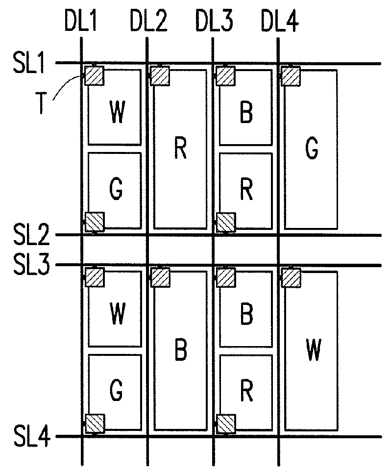
[0032]FIG. 5 is a top schematic of a repeating unit of a pixel array according to the invention. For ease of explanation, only one repeating unit 200 is illustrated in FIG. 5. However, those having ordinary skill in the art should understand that, a plurality of repeating units 200 can form the pixel array 1000 shown in FIG. 1. The repeating unit 200 of the present embodiment includes twelve sub-pixels that are respectively three first color sub-pixels R, three second color sub-pixels G, three third color sub-pixels B, and three fourth color sub-pixels W. Each of the first color sub-pixels R, the second color sub-pixels G, the third color sub-pixels B, and the fourth color sub-pixels W independently includes a scan line, a data line, and a driving element T. The driving element T is electrically connected to the scan line and the data line. As shown in FIG. 5, a repeating unit 200 of the present embodiment includes four scan lines SL1 to SL4 and four data lines DL1 to DL4, wherein t...
third embodiment
[0039]FIG. 9 is a top schematic of a repeating unit of a pixel array according to the invention. For ease of explanation, only one repeating unit 300 is illustrated in FIG. 9. However, those having ordinary skill in the art should understand that, a plurality of repeating units 300 can form the pixel array 1000 shown in FIG. 1. The repeating unit 300 of the present embodiment includes twelve sub-pixels that are respectively three first color sub-pixels R, three second color sub-pixels G, three third color sub-pixels B, and three fourth color sub-pixels W. Each of the first color sub-pixels R, the second color sub-pixels G, the third color sub-pixels B, and the fourth color sub-pixels W independently includes a scan line, a data line, and a driving element T. The driving element T is electrically connected to the scan line and the data line. In particular, as shown in FIG. 9, each repeating unit 300 of the present embodiment includes two scan lines SL1 and SL2 and six data lines DL1 ...
PUM
 Abstract
Description
Claims
Application Information