Battery charging apparatus and method

a battery and charging device technology, applied in the field of charging, can solve the problems of reducing charging time and overlong charging time, and achieve the effect of reducing charging time and quick charging for batteries

Active Publication Date: 2016-12-01
GUANGDONG OPPO MOBILE TELECOMM CORP LTD
View PDF3 Cites 29 Cited by
  • Summary
  • Abstract
  • Description
  • Claims
  • Application Information

AI Technical Summary

Benefits of technology

[0011]The disclosure adopts a battery charging apparatus which includes a power adapter and a charging control module; during charging the battery, the power adapter first charges the battery in a regular charging mode; when the output current value of the power adapter is within the regular current range for the predefined time period, the power adapter performs the quick charge inquiry communication with the charging control module; after the charging control module sends a quick charge command to the power adapter, the power adapter adjusts the output voltage according to the battery voltage information fed back by the charging control module; if such output voltage meets the quick charge voltage requirement predefined in the charging control module, the power adapter adjusts the output current and output voltage according to the quick charge mode so as to charge the battery, and the charging control module simultaneously introduces direct current from the power adapter to charge the battery, thus realizing a quick charge for battery to reduce the charging time.

Problems solved by technology

Currently, a battery of an electronic equipment is charged via its power adapter, while the power adapter typically charges the battery in a constant voltage output manner; however, for a high-storage battery, charging the battery in a constant voltage output manner may result in an overlong charging time, and hence the prior art above cannot realize a quick charge for battery to reduce the charging time.

Method used


Image

  • Battery charging apparatus and method
  • Battery charging apparatus and method
  • Battery charging apparatus and method

Examples


Embodiment Construction

[0024]In order to make the objective, the technical solutions and the advantages of the present disclosure more clear, the present disclosure is further described in details below in conjunction with the accompanying drawings and embodiments. It should be understood that the specific embodiments described herein are only used to explain the present disclosure, but not used to limit the present disclosure.

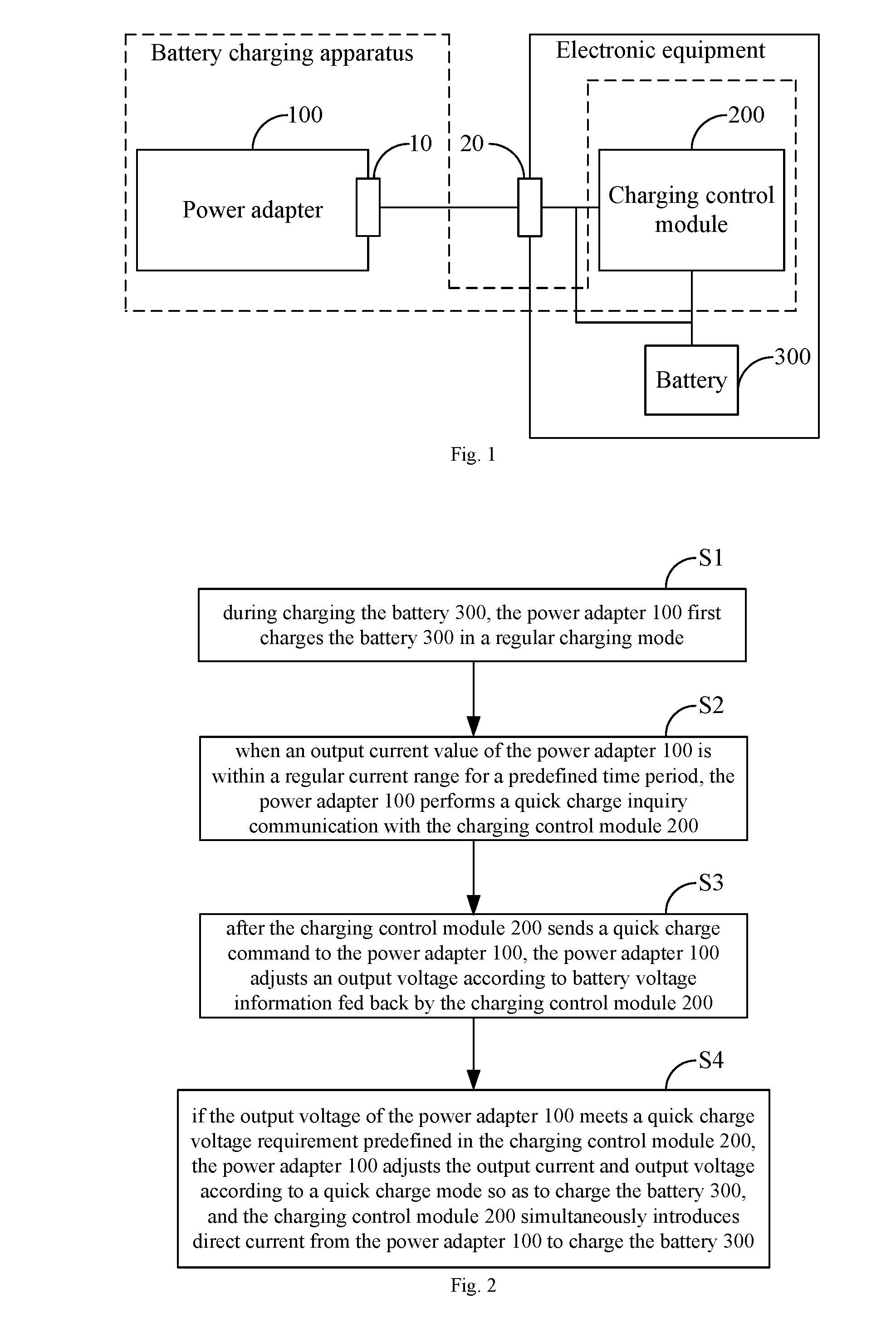
[0025]FIG. 1 shows a topology of a battery charging apparatus provided by an embodiment of the present disclosure, and for illustration purposes, only parts related to the embodiments of the present disclosure are shown, which will be described in details as follows.

[0026]The battery charging apparatus provided by an embodiment of the present disclosure includes a power adapter 100 and a charging control module 200. The power adapter 100 charges a battery 300 of an electronic equipment via a communication interface 10 thereof. The charging control module 200 is built in the electron...


PUM


Abstract

A battery charging apparatus and method. The battery charging apparatus comprises a power supply adapter (100) and a charging control module (200); during a process of charging a battery (300), the power supply adapter (100) charges a battery (300) in a routine charging mode; when an output current value of the power supply adapter (100) is within a routine current range at a preset time interval, the power supply adapter (100) communicates with the charging control module (200) for quick-charging query; after the charging control module (200) sends a quick-charging instruction command to the power supply adapter (100), the power supply adapter (100) regulates an output voltage according to battery voltage information fed back by the charging control module (200); and when the output voltage meets a quick charging voltage condition preset by the charging control module (200), the power supply adapter (100) regulates an output current and the output voltage in the quick-charging mode to charge the battery (300), and at the same time, the charging control module (200) introduces a direct current from the power supply adapter (100) to charge the battery (300), thereby achieving the objective of quickly charging the battery (300) to shorten the charging time.

Description

TECHNICAL FIELD[0001]The disclosure belongs to the technical field of charging and particularly relates to a battery charging apparatus and method.BACKGROUND[0002]Currently, a battery of an electronic equipment is charged via its power adapter, while the power adapter typically charges the battery in a constant voltage output manner; however, for a high-storage battery, charging the battery in a constant voltage output manner may result in an overlong charging time, and hence the prior art above cannot realize a quick charge for battery to reduce the charging time.DISCLOSURETechnical Problem[0003]The disclosure aims to provide a battery charging apparatus to solve the problem that the prior art cannot realize a quick charge for battery to reduce the charging time.Technical Solutions[0004]The disclosure is realized as follows. There is provided a battery charging apparatus which includes a power adapter and a charging control module; the power adapter charges via a communication inte...

Claims


Application Information

Patent Timeline
Patent Type & Authority Applications(United States)
IPC IPC(8): H02J7/00
CPCH02J7/0072H02J7/0052H02J2007/0059H02J7/0029H02J2007/0096H02J7/0042H02J7/045H02J2007/10H01M10/44H02J7/06H02J7/00H02J7/00714H02J7/007182H02J7/00304H02J7/00302H02J2207/30H02J7/00034H02J7/04H02J2207/20H02J7/0034
Inventor ZHANG, JIALIANGLIU, FENGSHUOWU, KEWEIPENG, LIANGCAILIAO, FUCHUNHU, YUANXIANG
Owner GUANGDONG OPPO MOBILE TELECOMM CORP LTD
Why Eureka
Try Eureka