Aircraft attitude indicator device

a technology of attitude indicator and aircraft, which is applied in the direction of indication devices, instruments, transportation and packaging, etc., can solve the problems of spatial disorientation, impairing the pilot's sensations, and affecting the pilot's perception of artificial horizons by pilots, so as to limit the risks of pilot loss of confiden

Active Publication Date: 2017-03-02
AIRBUS OPERATIONS (SAS)
View PDF2 Cites 0 Cited by
  • Summary
  • Abstract
  • Description
  • Claims
  • Application Information

AI Technical Summary

Benefits of technology

[0017]In particular, an aspect of the invention may limit the risks of spatial disorientation of the pilot, to prevent the pilot's sensations from being contradictory to the information which is given to him by the onboard instruments.
[0023]This aeroplane attitude indicator device makes it possible to corroborate the information provided by the artificial horizon and limits the risks of loss of confidence of the pilot.

Problems solved by technology

Despite this presentation of the information, the artificial horizon is perceived by pilots as an artificial aid, possibly prone to faults.
Indeed, the absence of any exterior visual frame, the flight conditions and stress may impair the pilot's sensations and give rise to spatial disorientation.
The loss of confidence, by the pilot, in the information given by the artificial horizon can then lead to situations of risk.

Method used


Image

  • Aircraft attitude indicator device
  • Aircraft attitude indicator device
  • Aircraft attitude indicator device

Examples


Embodiment Construction

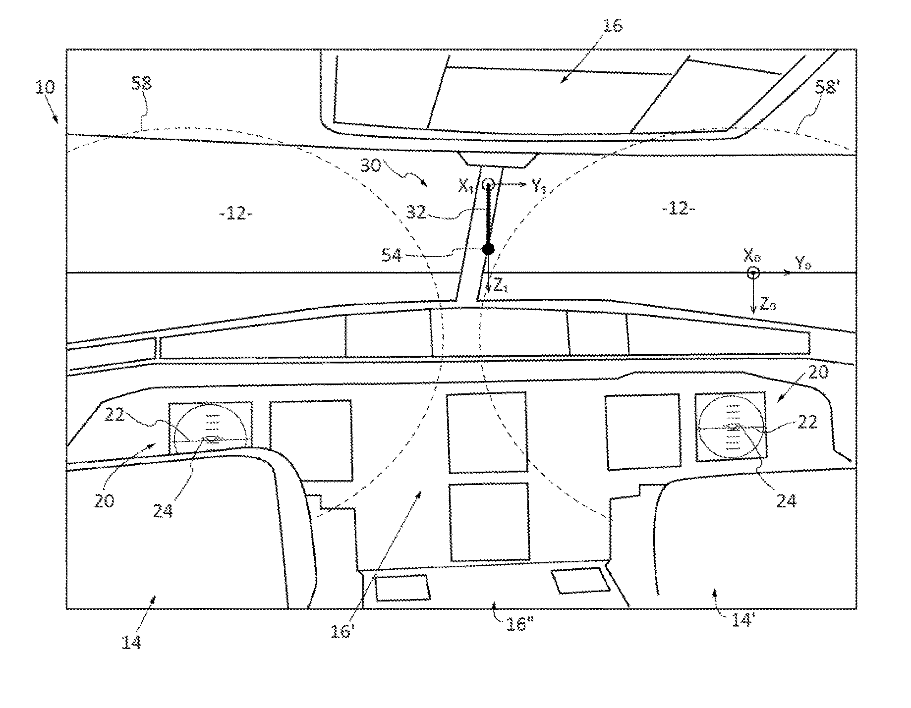
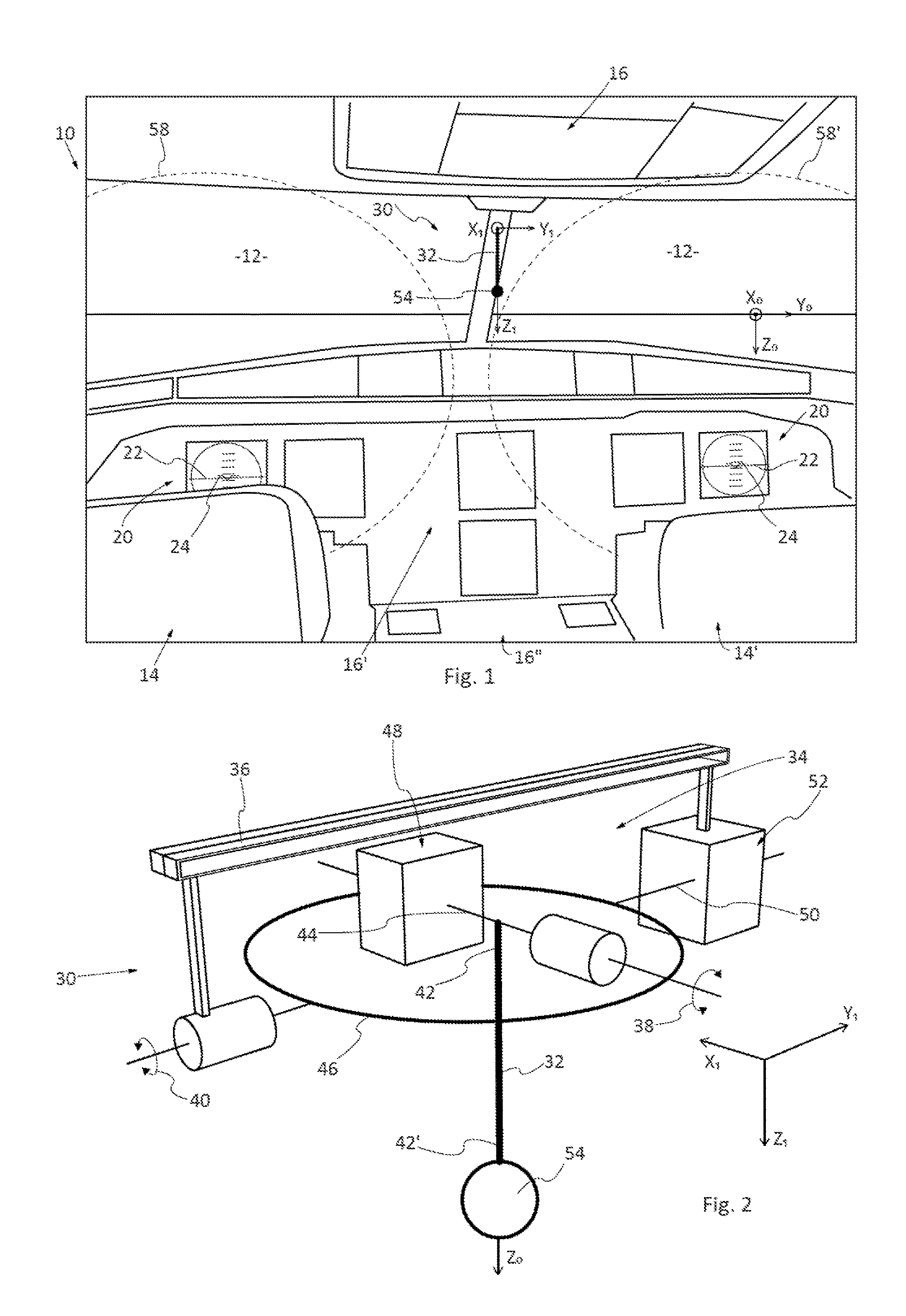
[0041]According to a configuration illustrated in FIG. 1, a cockpit of an aeroplane 10 comprises a windscreen 12, two piloting stations 14, 14′, a set of instrument panels 16, 16′, 16″ placed respectively above and below the windscreen 12 and between the two piloting stations, which comprise various onboard instruments such as viewing screens, controls, keyboards, etc. None of these elements is detailed further since they are known to the person skilled in the art. Moreover, the configurations of the cockpits vary from one model of aeroplane to another. In all cases, the cockpit of an aeroplane comprises at least one windscreen, at least one piloting station and at least one instrument panel.

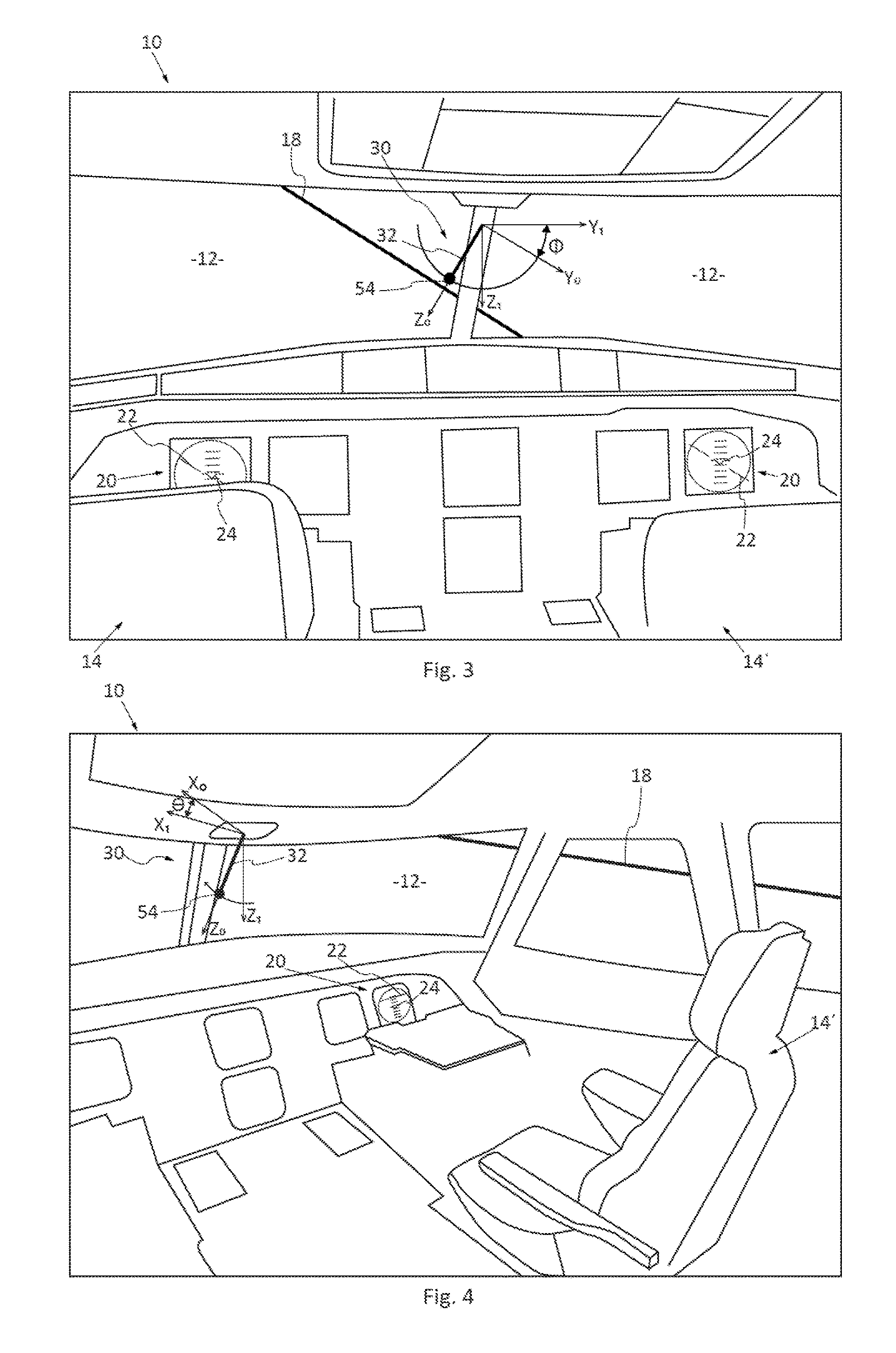
[0042]In FIGS. 1, 3 and 4, a real horizon line 18 perceived through the windscreen 12 has been represented in the form of a continuous line.

[0043]Among all the onboard instruments, the cockpit comprises an artificial horizon 20 which indicates the attitude of the aeroplane. According to one embo...


PUM


Abstract

An aeroplane attitude indicator device includes a mobile rod which includes a first end connected by a link to a support fastened to the aeroplane and a second end to which is connected a moving body, at least one actuator for controlling the motions of the rod, and a system for piloting the at least one actuator as a function of information originating from an attitude detection system of the aeroplane, so as to orient the rod in a vertical direction. The assembly of rod and moving body correspond to a pendulum-like artefact. Also described is an aeroplane cockpit equipped with an attitude indicator device.

Description

FIELD OF THE INVENTION[0001]The present invention pertains to an aircraft attitude indicator device.BACKGROUND OF THE INVENTION[0002]Hereinafter in this application, use is made of an earth frame of reference which comprises:[0003]An axis X0 which corresponds to a horizontal axis oriented northwards.[0004]An axis Y0 which is horizontal, perpendicular to the axis X0 and oriented eastwards.[0005]An axis Z0 which is perpendicular to the axes X0 and Y0 and oriented downwards.[0006]The axes X0 and Y0 define a horizontal plane and the axis Z0 corresponds to the vertical direction.[0007]To define the motions of an aeroplane, an aeroplane frame of reference is associated therewith, comprising:[0008]An axis X1 which extends from the rear tip to the front tip of the aeroplane and which is linked to the aeroplane, also called the aeroplane longitudinal axis X1,[0009]An axis Y1 which is perpendicular to the axis X1 and which is oriented in the direction of the aerofoil of the aeroplane, also ca...

Claims


Application Information

Patent Timeline
Patent Type & Authority Applications(United States)
IPC IPC(8): B64D43/02
CPCB64D43/02G01C21/16G01C19/44G01C21/18G01C15/14G01D13/22G01C9/005
Inventor LAINE, FRANCKSAPIN, OLIVIERRENAULT LEBERQUER, CHARLES
Owner AIRBUS OPERATIONS (SAS)
Why Eureka
Try Eureka