Release Mechanism for Clamping Tools

a technology of release mechanism and clamping tool, which is applied in the direction of clamps, manufacturing tools, and vices, etc., can solve the problems of thread slipping or jumping of the current art quick release button

Inactive Publication Date: 2017-10-12
TSUI GARY +2
View PDF0 Cites 3 Cited by
  • Summary
  • Abstract
  • Description
  • Claims
  • Application Information

AI Technical Summary

Benefits of technology

[0007]Present invention disclosed an improved release mechanism to release the clamp force applied by a vise or clamp, when a work piece is to be removed from the v

Problems solved by technology

However, the current art quick release button suffers from the disadvantage of th

Method used


Image

  • Release Mechanism for Clamping Tools
  • Release Mechanism for Clamping Tools
  • Release Mechanism for Clamping Tools

Examples


Embodiment Construction

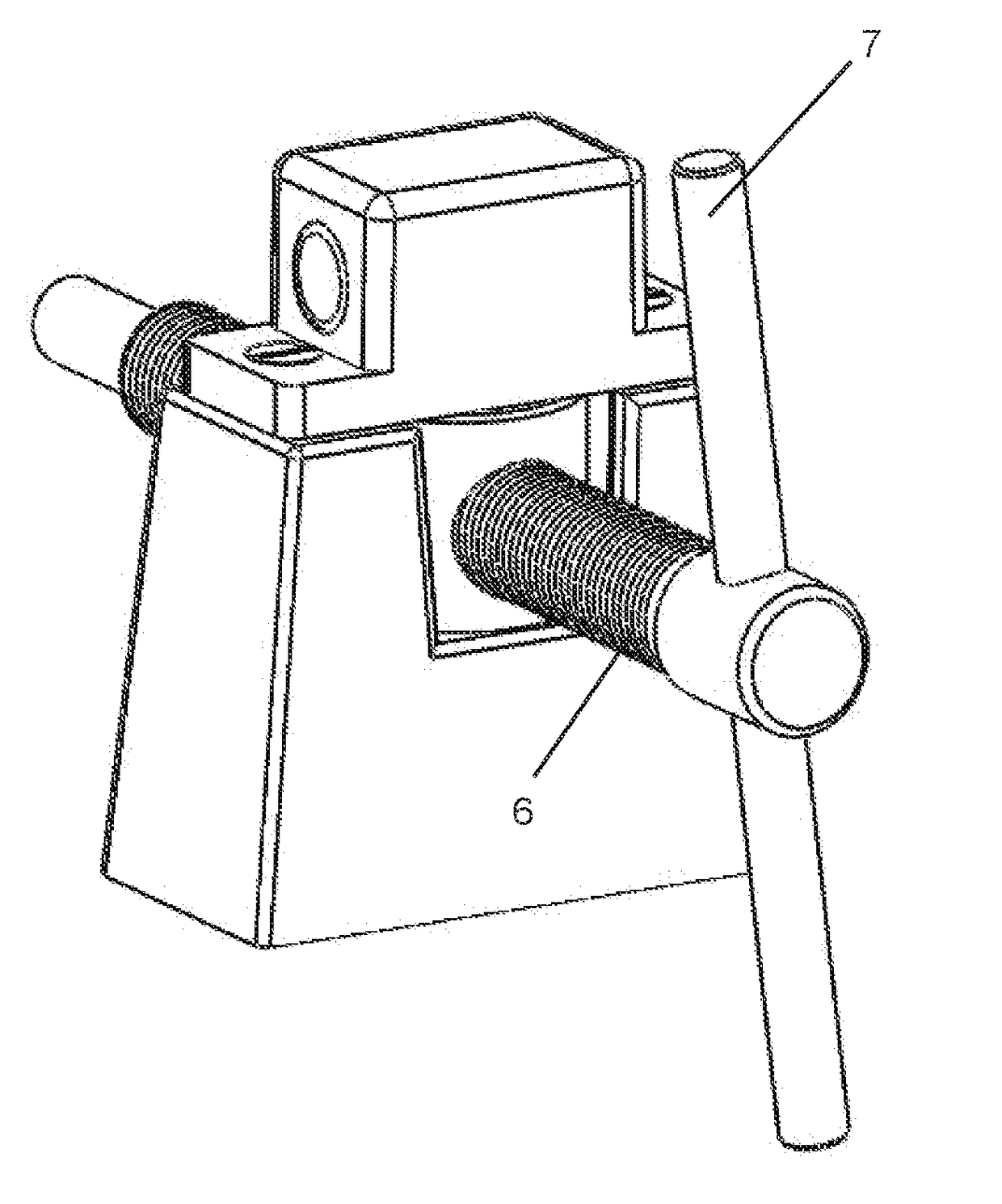
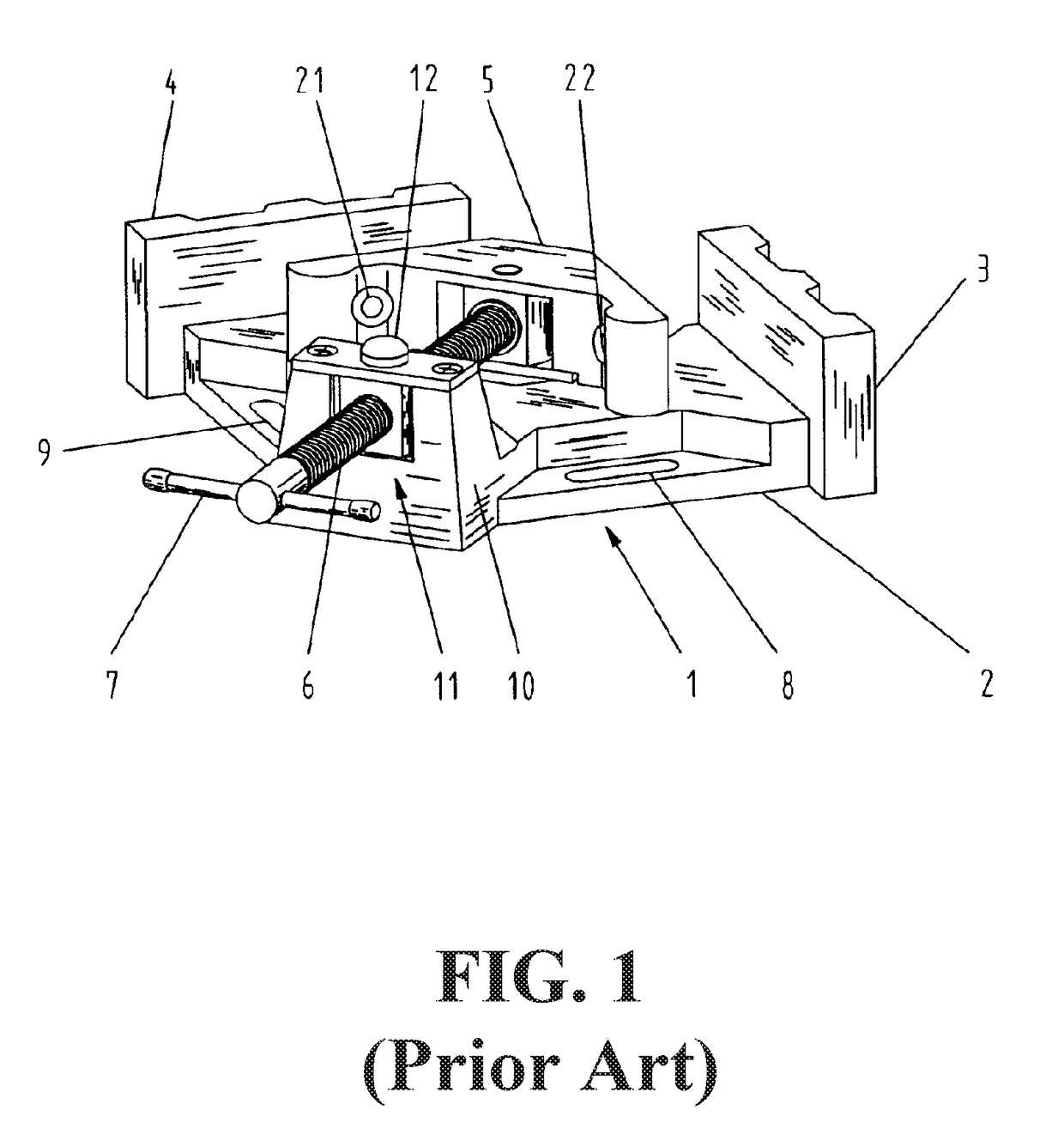
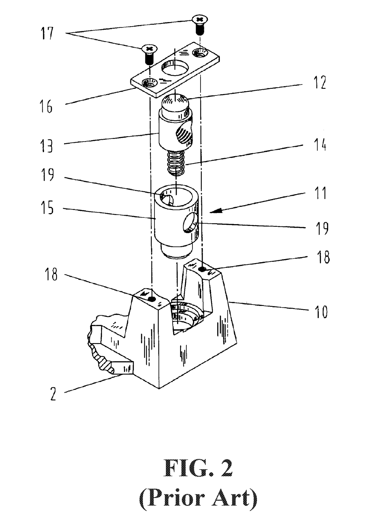
[0021]An example of current art quick release push button can be seen in the 475 Patent. The 475 Patent disclosed a clamping device which can be used to hold workpieces in a three dimensional 90-degree relationship with the addition of the Z-axis attachment. And the workpieces can easily be removed after work by pressing the quick acting push button to release the threaded shafts mounted with the clamping heads. The swing away clamping arm of the Z-axis attachment gives additional room for easier removal of the workpieces if necessary.

[0022]Such a clamp contains three mutually perpendicular base plates, one square shape bottom-plate and two smaller rectangular side-plates. The bottom-plate includes two slotted holes along two adjacent edges which are not connected to the side-plates, one along each edge, so that the angle clamp can be fixed to a work desk with two screws. The bottom-plate is equipped with a protruded ear at the vertex away from the side-plates. The ear is positioned...


PUM


Abstract

The present invention provides an improved release mechanism for clamping tools where problems of thread slipping due to worn out thread can be reduced by the structure of a plunger with a small diameter section and the engagement of the thread shaft is made more secure by the cam action on account of the shape of the plunger.

Description

FIELD AND BACKGROUND OF THE INVENTION[0001]The present invention relates to an improved mechanism for release of the clamp force when a work piece is being held in place by clamping tools or vises.[0002]Commercially available clamping tools oftentimes come with a “quick release” button where, instead of turning a gear / knob pitch-by-pitch to loosen the grip, a push on the button releases the engagement of the clamp parts to the work piece.[0003]The construction of such a release button invariably incorporated the element of a spring to provide the resilient force for keeping the engagement in place.[0004]As shown and discussed herein, the current art “quick release” mechanism may lead to thread slipping / jumping problem through repeated use of the device. Also, since the power to keep the work piece engagement is from the resilient force of the spring, the contact may not be too solid, once the spring starts to lose its resilience force, similarly through repeated use of the device.[0...

Claims


Application Information

Patent Timeline
IPC IPC(8): B25B1/12
CPCB25B1/125B25B5/142B25B5/166B25B1/12B25B5/10
Inventor TSUI, GARYLIU, WEINAMCHEN, SHAOSHENG
Owner TSUI GARY
Why Eureka
Try Eureka