Dynamic Solenoid Drive Duty Cycle Adjustment

a solenoid and drive technology, applied in the direction of motor parameters, pump parameters, piston pumps, etc., can solve the problems of increasing the cost of designing, developing, certifying, and reducing so as to minimize the impact on the overall cost and increase the efficiency of the pump. the effect of longevity

Active Publication Date: 2019-03-14
MILTON ROY
View PDF7 Cites 3 Cited by
  • Summary
  • Abstract
  • Description
  • Claims
  • Application Information

AI Technical Summary

Benefits of technology

[0009]An implementation using one or more of the above methods for determining an appropriate pulse width will be capable of automatically or manually adapting to a variety

Problems solved by technology

This is caused by the expansion and retraction of a diaphragm or displacement of the plunger within the chamber, which changes the overall volume of the chamber, thereby creating areas of low pressure or forcing liquid from the chamber.
In addition to variations in stable input voltage, some power sources may have noisy or unstable power input resulting in non-sinusoidal voltage waveforms.
These solutions may increase

Method used


Image

  • Dynamic Solenoid Drive Duty Cycle Adjustment
  • Dynamic Solenoid Drive Duty Cycle Adjustment
  • Dynamic Solenoid Drive Duty Cycle Adjustment

Examples


Embodiment Construction

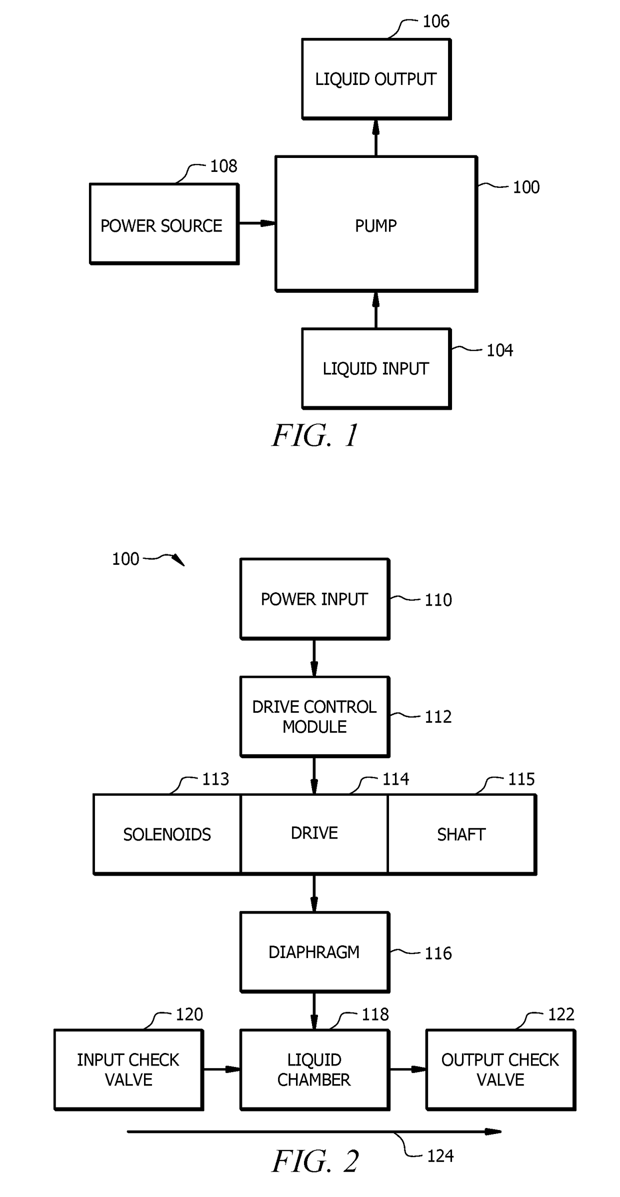
[0020]Referring now to FIG. 1, that figure is a schematic diagram showing an exemplary pump installation. Placement of the pump will depend upon a variety of factors, and may include, for example, considerations of the source of liquid that will be the liquid input (104) to the pump, the location where liquid will be pumped to as a liquid output (106), an available power source, and the form factor and other characteristics of the pump (e.g., whether it is designed to be horizontally or vertically mounted or placed, whether it is designed to be fully or partially submerged in liquid, whether the liquid input (104) is pulled through a hose attached to the pump (100), and other considerations). For the purposes of this disclosure, the pump (100) will be generally discussed as a solenoid driven diaphragm displacement pump. However, it should be understood that some or all of the concepts discussed herein will apply equally to a variety of pumps, including but not limited to plunger dis...


PUM


Abstract

The performance of a solenoid drive liquid pump can be very dependent on the magnitude and stability of an input voltage, with non-ideal input power resulting in loss of efficiency and potential damage to the pump. Pulse width of drive signals provided to the pump, which cause solenoids to alternately energize to move liquid through the pump, may be adjusted in duration in order to compensate for non-ideal input voltage. A drive control module of the pump gathers voltage information, determines an improved pulse width based upon that voltage information, and then provides drive signals based upon the improved pulse width. Operating in this manner, a pump can operate at or near peak efficiency despite both significant variances in input voltage and non-sinusoidal input voltage, and without customized components or adapters.

Description

CROSS REFERENCE TO RELATED INFORMATION[0001]This application claims the benefit of U.S. Provisional Patent Application No. 62 / 558,486, filed Sep. 14, 2017, titled Dynamic Solenoid Drive Duty Cycle Adjustment, the contents of which are hereby incorporated herein in its entirety.TECHNICAL FIELD[0002]The present disclosure is directed to a system and method for dynamically adjusting drive duty cycle to account for varying conditions of power input to a pump.BACKGROUND OF THE INVENTION[0003]Positive displacement solenoid drive pumps operate by energizing a coil to create a magnetic field that moves a shaft within the pump. The movement of the shaft within a chamber of the pump can displace liquids or gases within chamber by, for example, the movement of a plunger or diaphragm attached to the shaft drawing liquid into the pumping chamber through an inlet check valve or forcing liquid from the pumping chamber through an outlet check valve. The displacement caused by the plunger or diaphra...

Claims


Application Information

Patent Timeline
IPC IPC(8): F04B49/03F04B45/047F04B35/04F04B17/04
CPCF04B49/03F04B45/047F04B35/045F04B17/04F04B49/065F04B13/00F04B43/0081F04B43/04F04B2201/0202F04B2201/0206F04B2203/0402F04B2203/0405F04B2203/0409F04B2205/03F04B49/20F04B49/16F04B49/12
Inventor CARMAN, JASONFAIRFIELD, NILE
Owner MILTON ROY
Why Eureka
Try Eureka