Lighting elevating apparatus

a technology of elevating apparatus and lighting, which is applied in the direction of lighting support devices, hoisting equipment, lighting applications, etc., can solve the problems of entanglement of reel wires, heavy burden on suspension batons, and high risk of dropping lighting elevating apparatuses in the middle of stage performances, and achieves simple structure

Active Publication Date: 2019-03-14
ISA
View PDF12 Cites 5 Cited by
  • Summary
  • Abstract
  • Description
  • Claims
  • Application Information

AI Technical Summary

Benefits of technology

[0011]The structure of the lighting elevating apparatus according to an embodiment of the present invention allows the reel wire free from displacement and / or slack only by providing a reeling guide that contacts with the reel wire. Further, no other component to avoid the displacement and / or slack of the reel wire is required to achieve the lightweight and simple structure.

Problems solved by technology

Under such circumstances, multiple lighting elevating apparatuses are suspended from the suspension baton, thereby causing tremendous burden on the suspension baton.
Further, the more the lighting elevating apparatus weighs, the higher the risk of dropping the lighting elevating apparatus in the middle of the stage performance becomes.
However, in the above-described lighting elevating apparatus, due to a displacement (see FIG. 1A) and / or a slack (see FIG. 1B) of the reel wire in reeling the reel wire on the reel, the reel wire is entangled and such entanglement stops the elevation of the lighting element.
Accordingly, the elevation type luminaire of PTL 2 does not completely prevent the occurrence of the displacement and / or slack in reeling up a reel wire.

Method used


Image

  • Lighting elevating apparatus
  • Lighting elevating apparatus
  • Lighting elevating apparatus

Examples


first embodiment

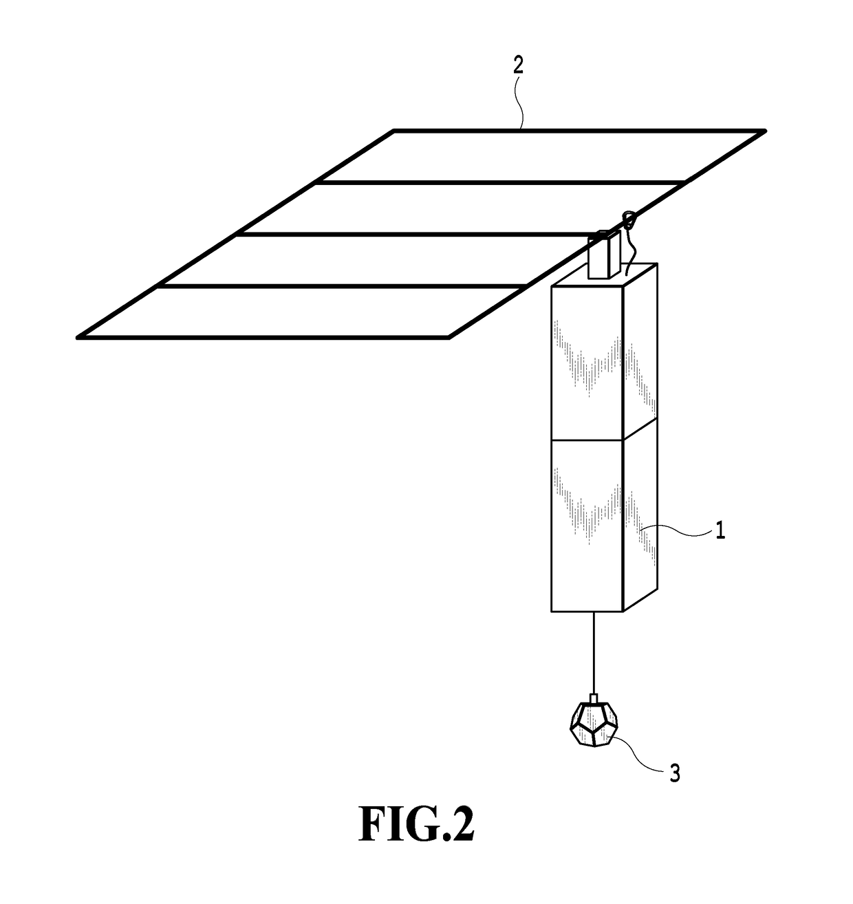
[0027]FIG. 2 is a view showing an entire lighting system according to a first embodiment of the present invention. The lighting system includes a lighting elevating apparatus 1, a suspension baton 2, and a lighting element 3. The upper end of the lighting elevating apparatus 1 is coupled to the suspension baton 2 and is suspended from the suspension baton 2. As shown in FIG. 2, the lighting elevating apparatus 1 is suspended with its longitudinal direction being vertically set. The lighting elevating apparatus 1 uses an electric motor provided therein to rotate the reel, whereby the reel wire having the lighting element 3 attached thereto is reeled on the reel and unreeled from the reel to cause the lighting element 3 to ascend / descend. The elevation of the lighting element 3 is controlled by a control device (not shown) connected to the lighting elevating apparatus 1 through software control.

[0028]The suspension baton 2 is a stage mechanism which is arranged on the ceiling of the s...

second embodiment

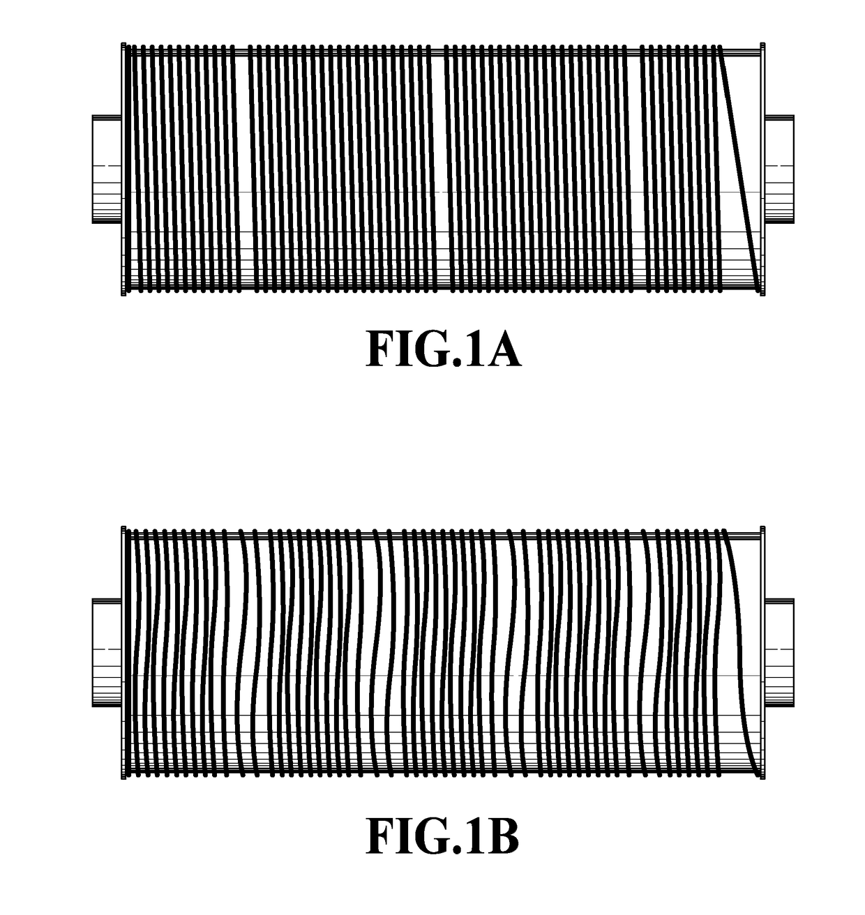
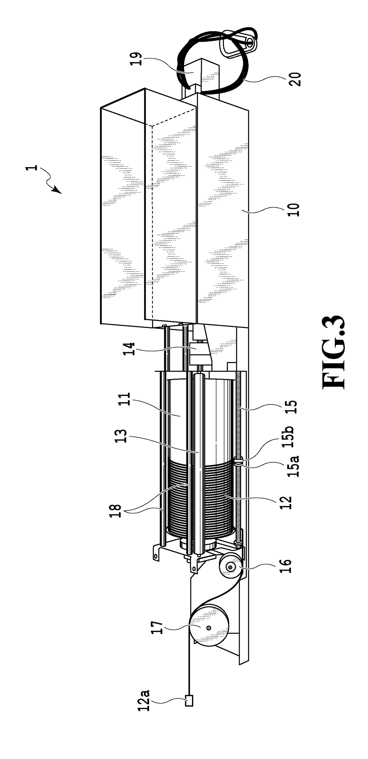
[0060]Next, with reference to FIG. 9, the lighting elevating apparatus 1 according to a second embodiment of the present invention will be explained. In comparison of the lighting elevating apparatus 1 according to the present embodiment with the lighting elevating apparatus according to the first embodiment, a difference is found in the guide screw 15. As shown in FIG. 9, the guide screw 15 includes a guide block 21, and includes a reel wire fixing part 22 below the guide block 21, and further includes a guide ring 23 below the reel wire fixing part 22.

[0061]The guide block 21 has a surface facing the reel wire reeling face 11a. The guide screw 15 is inserted through an axial bore of the guide block 21, which moves vertically along the guide screw 15 in conjunction with the rotation of the guide screw 15. This vertical movement is configured to interlock the reeling of the reel wire 12 on the reel wire reeling face 11a. A small clearance exists between the reel wire reeling face 11...


PUM


Abstract

A lighting elevating apparatus includes: a reel coupled to a motor and rotated around an axis of a surface in a short direction of the reel including a reel wire reeling face and being arranged such that its longitudinal direction is in a vertical state; a reel wire to be reeled on the reel wire reeling face; a reeling guide including a reel wire touching part facing the reel wire reeling face and being arranged in parallel to the reel, wherein a distance between the reel wire reeling face and the reel wire touching part is equal or less than a diameter of the reel wire; and a connector attached to an end of the reel wire to connect an object, wherein the reeling guide counter-rotates, and the reel wire passes between the reel wire reeling face and the reel wire touching part.

Description

TECHNICAL FIELD[0001]The present disclosure relates to a lighting elevating apparatuses, and in particular, relates to a lighting elevating apparatus which elevates a lighting element for applying illumination light from above a stage in stage direction.BACKGROUND ART[0002]In stage direction for supporting presenters to perform productions such as plays and dances, stage lighting systems are used. Such stage lighting systems are roughly classified, according to their installing locations, into a lighting system that applies light from above a stage, a lighting system that applies light from the floor surface of the stage, a lighting system that applies light from the side of the stage, and a lighting system that applies light from audience seating. The lighting system that applies light from above the stage (hereinafter referred to as an “above-stage lighting system”) elevates the lighting element which is connected to a reel wire and suspended from a suspension baton. The suspensio...

Claims


Application Information

Patent Timeline
Patent Type & Authority Applications(United States)
IPC IPC(8): F21V21/16F21V21/38F21S8/06
CPCF21V21/16F21V21/38F21S8/061F21W2131/406F21V21/36F21V27/00B66D1/38B66D1/28
Inventor ISAYAMA, KIYOSHI
Owner ISA
Why Eureka
Try Eureka