Rolling equipment intended to be ridden by a child

a technology for rolling equipment and children, applied in the direction of bicycles, transportation and packaging, and vehicles with multiple axes, can solve the problems of bulky equipment, and achieve the effect of reducing volume and easy and quick folding

Inactive Publication Date: 2019-07-11
ID DEV
View PDF3 Cites 6 Cited by
  • Summary
  • Abstract
  • Description
  • Claims
  • Application Information

AI Technical Summary

Benefits of technology

[0013]In the unfolded state of the equipment, the slider is held by said holding device in said lower position and therefore positions the legs at a distance from said median front pillar and at a distance from the seat; in this state, the axes of the different wheels of the equipment are in a plane substantially parallel to a plane in which the seat generally extends, and located at a distance from this seat, so that the equipment can b

Problems solved by technology

These equipments are often bulky and occupy an

Method used


Image

  • Rolling equipment intended to be ridden by a child
  • Rolling equipment intended to be ridden by a child
  • Rolling equipment intended to be ridden by a child

Examples


Embodiment Construction

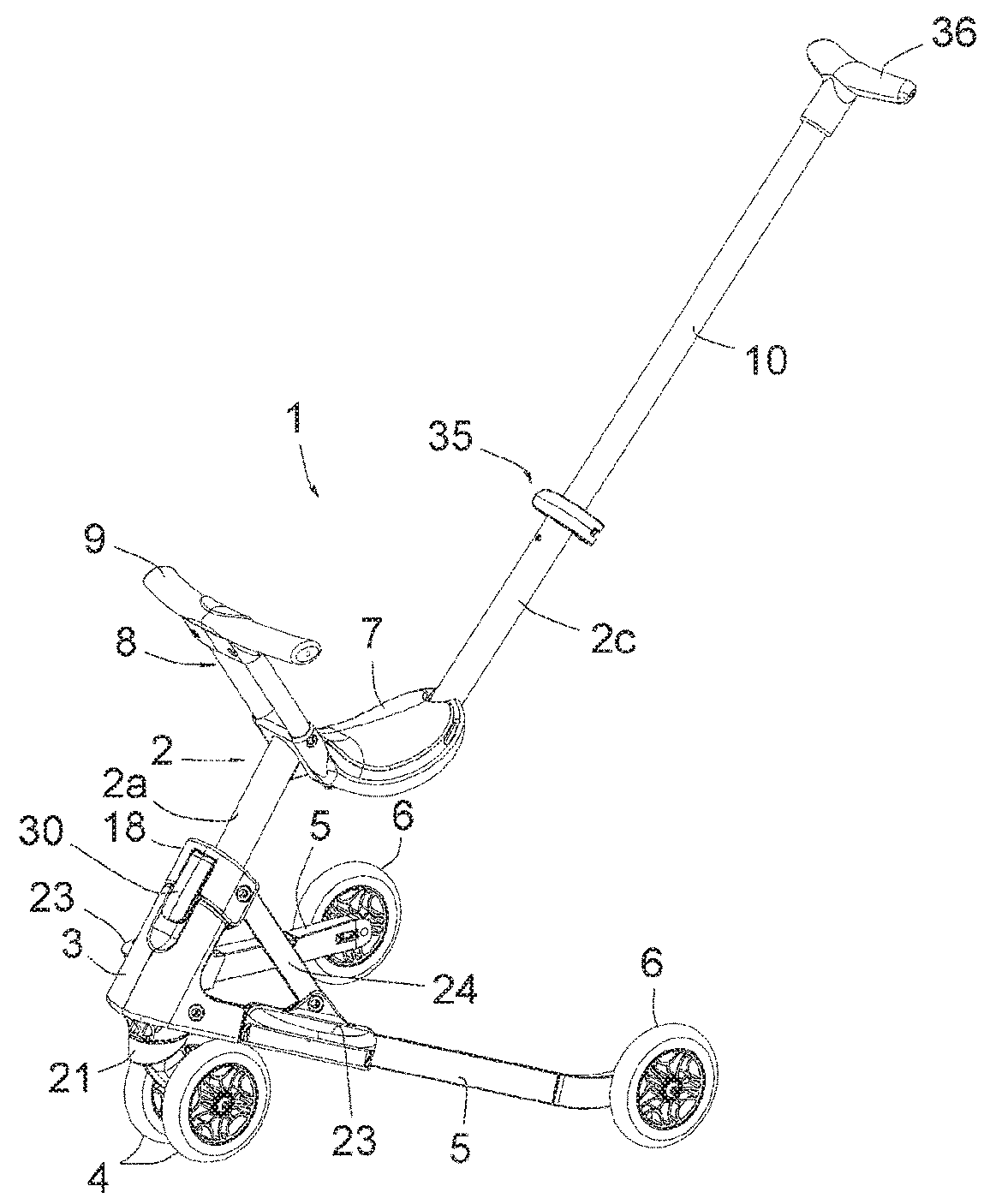
[0044]FIG. 1 shows a rolling equipment or vehicle 1 intended to be straddled by a child, consisting essentially of a middle structural element 2, a lower base part 3, a pair of front wheels 4, two pivotable legs 5, rear wheels 6, a seat 7, a post 8 in front of the seat 7, having a crossbar 9, and an oblique rear rod 10.

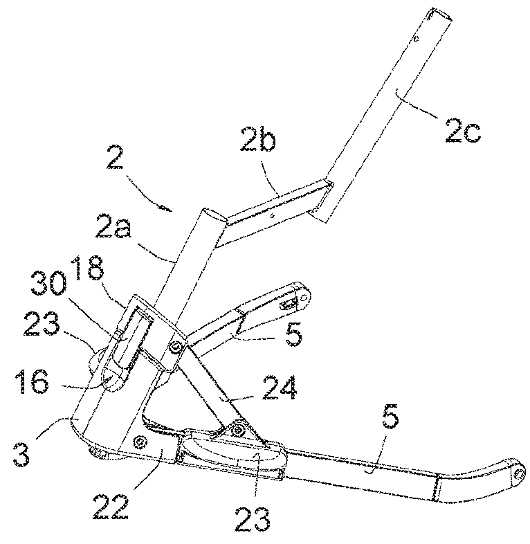
[0045]The middle structural element 2 is most visible in FIG. 2, where seat 7, post 8, bar 9 and handle 10 have been removed. As can be seen, this element 2 includes a lower front pillar 2a, a median cross member 2b and an upper rear post 2c.

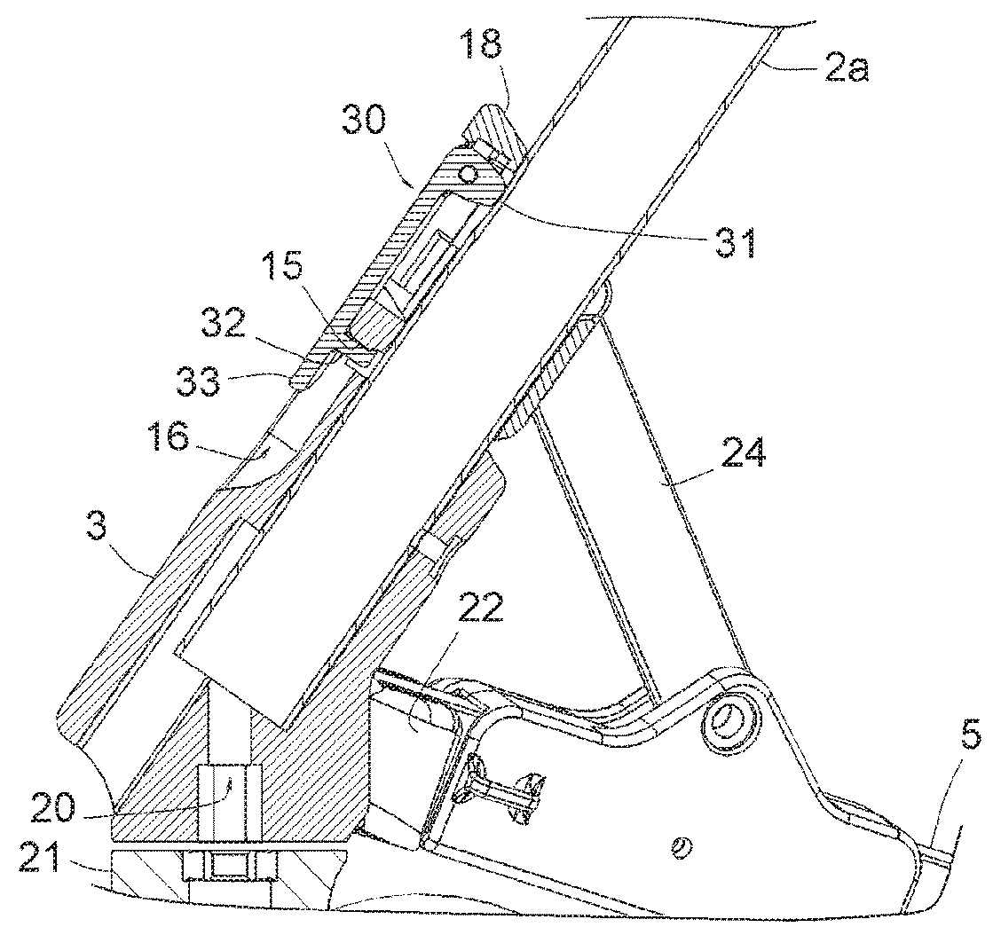
[0046]With reference to FIGS. 1 to 3, it appears that the lower front pillar 2a is inclined towards the rear and that it is attached to the lower part of the lower base part 3. The connection between this pillar 2a and base part 3 is made by screws, the base part 3 including for this purpose at least one screw hole visible in FIG. 3.

[0047]The median cross member 2b is intended to receive and support the seat 7.

[0048]The upper rea...


PUM


Abstract

The equipment (1) includes: a median front pillar (2a), provided with at least one front wheel (4) at its lower end; a seat (7) located at the upper end of the front median pillar (2a); two pivotable legs (5), pivotally connected, by a front end, to a lower part of the median front pillar (2a), and each including a wheel (6) at a rear end; a slider (18) slidably movable along the front median pillar (2a), and two connecting rods (24) connected to the slider (18), on two opposite sides thereof, and connected to the legs (5); the slider (18) is movable between a lower position, in which the connecting rods (24) bring the legs (5) into the unfolding position and an upper position, in which the connecting rods (24) bring the legs (5) into the folding position; and releasable device (30) for holding the slider (18) in the lower position.

Description

[0001]This invention concerns a rolling equipment intended to be ridden by a child.BACKGROUND OF THE INVENTION[0002]There are different kinds of equipment designed to be ridden by children. These equipments are often bulky and occupy an important place in a dwelling when not in use.OBJECTS OF THE INVENTION[0003]The purpose of this invention is to remedy this significant disadvantage.[0004]There are also folding equipment available; these equipments are not always very easy and fast to unfold and therefore do not give perfect satisfaction.[0005]The present invention also aims to remedy this disadvantage.SUMMARY OF THE INVENTION[0006]To achieve at least one of the objects mentioned above, the equipment according to the invention shall comprise:[0007]a median front pillar having lower end and an upper end, comprising at least one front wheel at the lower end;[0008]a seat located at the upper end of the front median pillar;[0009]two pivotable legs having a front end and a rear end; the ...

Claims


Application Information

Patent Timeline
IPC IPC(8): B62B7/04B62B7/06
CPCB62B7/044B62B7/06B62B3/001B62B3/022B62B3/12B62B7/002B62B9/20B62B9/02B62K3/002B62K5/02B62K9/02
Inventor MAZOYER, JOSEPHBAJARD, PHILIPPE
Owner ID DEV
Why Eureka
Try Eureka