Image forming apparatus that performs display for replacement of developer container, and method of controlling same

Inactive Publication Date: 2019-10-17
CANON KK
View PDF12 Cites 0 Cited by
  • Summary
  • Abstract
  • Description
  • Claims
  • Application Information

AI Technical Summary

Benefits of technology

The present invention relates to an image forming apparatus that can display messages to prompt a user to replace the container containing remaining developer when the container is either mounted or removed. The technical effect is that the image forming apparatus can provide appropriate display based on the predetermined condition related to the amount of remaining developer in the developing device, making it convenient for the user to replace the container when necessary.

Problems solved by technology

The amount of developer which can be stored in the developing unit is limited, and hence developer is replenished from a container which can be mounted on and removed from the image forming apparatus, as required.
Further, the amount of developer in the container is also limited, and hence if the developer in the container runs out, the developer cannot be replenished from the container to the developing unit.
Incidentally, there is a case where the image forming apparatus cannot normally detect mounting of a container even though the user has mounted the container on a mount section.
For example, the user may unnecessarily repeat mounting and removal of the container.
In this image forming apparatus, if a screen different from the warning screen is displayed due to closing of the door, there is no longer an opportunity for prompting the user again to remount the removed container.
Therefore, since it is impossible to notify the user again that the container can still be used, the container containing remaining developer can be wastefully discarded.
This results in unnecessary replacement of the container.

Method used


Image

  • Image forming apparatus that performs display for replacement of  developer container, and method of controlling same
  • Image forming apparatus that performs display for replacement of  developer container, and method of controlling same
  • Image forming apparatus that performs display for replacement of  developer container, and method of controlling same

Examples


Embodiment Construction

[0030]The present invention will now be described in detail below with reference to the accompanying drawings showing embodiments thereof.

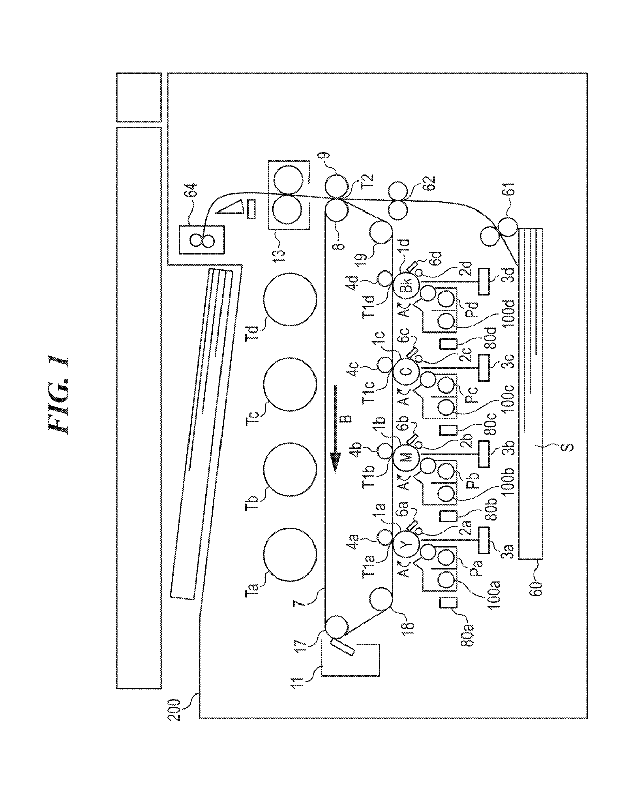
[0031]FIG. 1 is a view of an image forming apparatus according to an embodiment of the present invention. This image forming apparatus, denoted by reference numeral 200, includes a plurality of image forming sections P (Pa, Pb, Pc, and Pd) for forming images of different colors, respectively. The image forming sections Pa, Pb, Pc, and Pd form toner images of yellow (Y), magenta (M), cyan (C), and black (Bk), respectively. In a main body of the image forming apparatus 200, there are removably provided toner containers T (Ta, Tb, Tc, and Td) for storing developer (toner) of the colors corresponding to the image forming sections Pa, Pb, Pc, and Pd, respectively. Each toner container T is also referred to as the toner bottle or the storage container. The toner container Ta stores toner of yellow and replenishes the toner of yellow to the image forming...


PUM


Abstract

An image forming apparatus capable of performing appropriate display when a container containing remaining developer is removed from a mount section. A controller of the image forming apparatus determines whether the amount of developer remaining in the container mounted on the mount section is larger than a predetermined amount. If a predetermined condition related to the amount of remaining developer in a developing device is satisfied, in a state where the container is mounted on the mount section, a first screen is displayed for prompting a user to replace the mounted container is displayed. If the predetermined condition is satisfied in a state where the container containing remaining developer in an amount larger than the predetermined amount has been removed from the mount section, a second screen is displayed for prompting the user to remount the removed container.

Description

BACKGROUND OF THE INVENTIONField of the Invention[0001]The present invention relates to an image forming apparatus on and from which a container containing developer can be mounted and removed, and a method of controlling the same.Description of the Related Art[0002]An electrophotographic image forming apparatus forms an image by developing an electrostatic latent image formed on a photosensitive member using developer in a developing unit (developing device). The amount of developer which can be stored in the developing unit is limited, and hence developer is replenished from a container which can be mounted on and removed from the image forming apparatus, as required. Further, the amount of developer in the container is also limited, and hence if the developer in the container runs out, the developer cannot be replenished from the container to the developing unit. Therefore, in a case where the developer in the container runs out, the image forming apparatus notifies the user of t...

Claims


Application Information

Patent Timeline
IPC IPC(8): G03G15/00G03G21/16
CPCG03G15/556G03G21/1633G03G15/0856G03G15/0879G03G15/502
Inventor MATSUMOTO, HIDENORIMANDACHI, YOJIRO
Owner CANON KK
Why Eureka
Try Eureka