Illuminated support rails for pinball machines

Pending Publication Date: 2022-04-07
MEUNIER ERIC M +3
View PDF14 Cites 0 Cited by
  • Summary
  • Abstract
  • Description
  • Claims
  • Application Information

AI Technical Summary

Benefits of technology

[0015]The disclosed lighted support rails provide both mechanical stability to the playfield, as well as additional illumination and optional mounting locations for decorative features and/or game mechanisms. Channels or grooves used to affix the rail to the playfield, and to mount objects to the rail, provide flexibility in locating mounting components or

Problems solved by technology

Because the wooden playfields 100 are precisely shaped and routed, contain painted or printed artwork on the top surface, and are often clearcoated to protect the graphics and wood beneath, they can be costly and time-consuming to produce.
However, illumination of such inserts does not provide direct lighting of the upper playing surface, as the light source lies beneath the playfield 100.
Considerat

Method used


Image

  • Illuminated support rails for pinball machines
  • Illuminated support rails for pinball machines
  • Illuminated support rails for pinball machines

Examples


Embodiment Construction

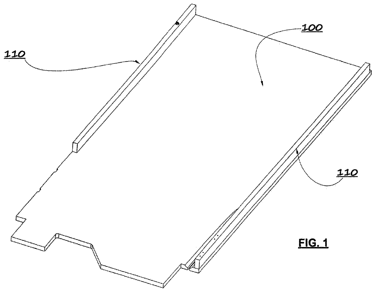
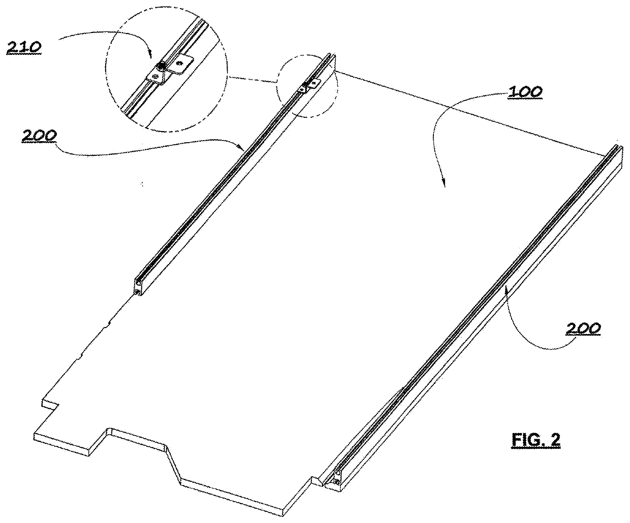
[0036]Embodiments of the present disclosure can provide side support rails for a pinball machine playfield that can facilitate improved illumination of the playing surface without obstructing playfield features. Support rails are already present on essentially all pinball playfields 100, and embodiments of the disclosure can be used to provide stability to the playfield 100 as well as to provide improved and unobtrusive illumination for pinball machines and the like. The disclosed support rails can provide certain benefits as described herein yet not interfere with ball movement or take up available space on the playfield 100. They can be substantially the same size as existing (e.g., wooden) support rails, while further providing a platform for easily mounting and / or relocating of illuminating elements and / or certain mechanisms or decorations in the machine, again without interfering with any available playfield area in the game.

[0037]An exemplary embodiment of the present disclosu...


PUM


Abstract

Support rails are provided for pinball machine playfields that provide mechanical support as well as light-emitting elements, such as LEDs, that generate additional light for illuminating the playfield and/or decorative features affixed to the rails. At least a portion of the support rail is preferably made of a transparent or translucent material to facilitate transmission of light from lighting elements below or enclosed by the rail. The support rails can be provided with various grooves, channels, and holes to facilitate mounting of the rails to a playfield or an existing support rail, using nuts and bolts, screws, brackets, and the like. The lighted support rails provide both mechanical stability to the playfield, as well as additional illumination and optional mounting locations for decorative features and/or game mechanisms. These functions of the support rail can be achieved without taking up room on the ‘active’ area of the playfield itself or obstructing visibility of the playfield and its components.

Description

BACKGROUND INFORMATION[0001]The pinball industry has exhibited a resurgence in recent years, with several new companies producing new machines. It has also become a collector's hobby, with many people now buying new and older games for home use.[0002]A typical pinball machine includes a substantially rectangular wooden cabinet standing on four corner legs, with an inclined flat playfield mounted within the cabinet and a glass sheet enclosing the upper surface of the cabinet. A vertical box structure, referred to as a backbox, is typically mounted at the rear of the cabinet. The backbox can contain a panel of static artwork (e.g., a backglass or translite), one or more displays to show scores, describe game features and / or animated or varying artwork, and speakers for audio effects. The backbox can also contain additional components such as control circuitry, lighting elements, power components, and the like.[0003]A conventional playfield 100 is illustrated in FIG. 1. The playfield 1...

Claims


Application Information

Patent Timeline
IPC IPC(8): A63F7/36A63F7/02F21S4/28F21V19/00
CPCA63F7/36A63F7/027F21Y2115/10F21V19/003F21S4/28A63F2009/2454F21V33/008
Inventor MEUNIER, ERIC M.MOLTER, DANIEL E.JOHNSON, KEITH P.BROWN, DUNCAN F.
Owner MEUNIER ERIC M
Why Eureka
Try Eureka