Output apparatus and method for controlling the same

a technology of output apparatus and control method, which is applied in the direction of digital output to print units, instruments, computing, etc., can solve the problems of increasing manufacturing cost, reducing productivity, and weakening the cost associated with the dispatch of service engineers in recent years, and achieves the effect of increasing cos

Active Publication Date: 2022-04-21
CANON KK
View PDF1 Cites 0 Cited by
  • Summary
  • Abstract
  • Description
  • Claims
  • Application Information

AI Technical Summary

Benefits of technology

This solution enables the proper operation of multiple consumables in output apparatuses, reducing costs and downtime by allowing common consumables and mode switching, thereby improving productivity and reducing manufacturing expenses.

Problems solved by technology

However, a request to reduce the down time for maintaining the image forming apparatuses and the cost associated with the dispatch of service engineers has recently become stronger.
However, shaping the hardware of the image forming apparatus or the consumables differently according to the difference in operation type makes it impossible to share the consumables, resulting in a decrease in productivity and an increase in manufacturing cost.
In contrast, shaping the consumables or the installation portions in common and allowing the manager to change the mode of the image forming apparatus, as in the image forming apparatus disclosed in Japanese Patent Laid-Open No. 2008-137333, can cause misplacement of unintended consumables.
However, providing the RFID tags on the consumables, such as an ITB unit, has difficulties such as limiting the attaching position.
Furthermore, an increase in the kind of consumables to be replaced by the user can cause misplacement of the various consumables.

Method used


Image

  • Output apparatus and method for controlling the same
  • Output apparatus and method for controlling the same
  • Output apparatus and method for controlling the same

Examples


first embodiment

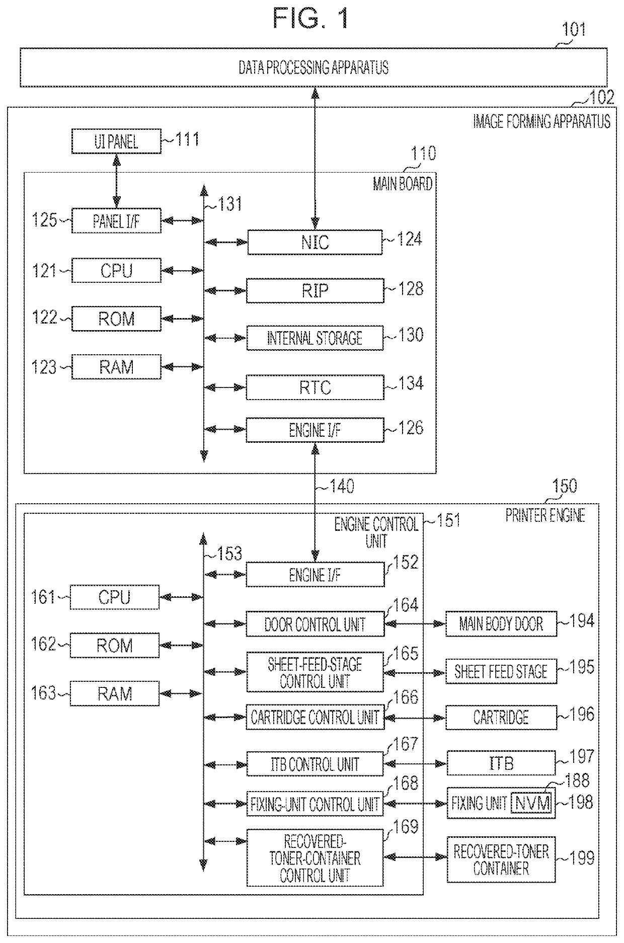
[0030]In a first embodiment, the operation type of a fixing unit 198 is read from a non-volatile memory (NVM) 188 provided in the fixing unit 198. An ITB 197 is initialized based on the operation type of the fixing unit 198, and the status of the ITB 197 and a message on the ITB 197 are determined by way of example. This is an example in which the fixing unit 198 is used in the determination of an engine control unit 151 in consideration of the replacement frequency and the ease of replacement of the fixing unit 198.

[0031]FIG. 1 is a block diagram illustrating the module configuration of an image forming apparatus 102, which is an example of the output apparatus.

[0032]A data processing apparatus 101 (for example, a personal computer [PC]) creates page description language (PDL) data and transmits the created PDL data to the image forming apparatus 102. The PDL data contains various instructions necessary for image formation including a drawing command for data on an image to be form...

second embodiment

[0170]A second embodiment is an example in which the operation types of consumables installed at factory shipment are used.

[0171]At factory shipment, consumables are installed according to the operation type of the image forming apparatus 102 main body. For that reason, storing the operation types of the consumables installed during the production process in the image forming apparatus 102 main body allows the initialization processing of the consumables to be executed without depending on the operation types of the other consumables.

[0172]FIG. 8 is a flowchart for a consumable initialization processing executed by the engine control unit 151.

[0173]Since the second embodiment is substantially similar to the first embodiment, a description will be given focusing on S821 to S851, which are executed instead of S221 to S253.

[0174]The engine firmware first performs the same processing from S201 to S203 of the first embodiment (S801).

[0175]The engine firmware switches processes depending ...


PUM


Abstract

An output unit determines whether a plurality of consumables installed in the output apparatus, such as a fixing unit and a transfer belt unit, are properly installed based on information on the main body of the output apparatus and information on the consumables. When the consumables are not properly installed, the output unit issues a message indicating a warning or an error to the user.

Description

CROSS-REFERENCE TO RELATED APPLICATIONS[0001]This application is a continuation application of U.S. patent application Ser. No. 16 / 221,099, filed on Dec. 14, 2018, which claims the benefit of Japanese Patent Application No. 2017-241486, filed Dec. 18, 2017, which is hereby incorporated by reference herein in its entirety.BACKGROUNDField of the Disclosure[0002]The present disclosure relates to output apparatuses in which consumables are installed.Description of the Related Art[0003]Output apparatuses that produce an output using consumables are known in the art. One example is an output apparatus that forms an image on a sheet based on print data. Output apparatuses typified by an image forming apparatus in business have a charge operation type and a non-charge operation type. In the charge operation type, consumables are provided to customers free of charge, and a usage fee corresponding to the print counter of the image forming apparatus main body is collected from the customers. I...

Claims


Application Information

Patent Timeline
Patent Type & AuthorityApplications(United States)
IPC IPC(8): G06F3/12
CPCG06F3/1235G06F3/1278G06F3/1285G06F3/121G06F3/1203G06F3/1219
InventorSASAKI, HIDEMI
OwnerCANON KK