Implantable injection port

a technology of injector port and connector, which is applied in the direction of infusion needle, medical preparation, other medical devices, etc., can solve the problems of flange collapse, and none of the prior art injection ports provid

Inactive Publication Date: 2000-03-21
FOGARTY TERENCE M
View PDF44 Cites 239 Cited by
  • Summary
  • Abstract
  • Description
  • Claims
  • Application Information

AI Technical Summary

Problems solved by technology

None of the prior art injection ports provide a port that provides a low profile, a large septum that can withstand high operating pressures, a housing connector assembly without welding, soldering or bonding, light weight, very low residual volume and a connector flange that is collapsed, not press fit with galled surfaces.

Method used


Image

  • Implantable injection port
  • Implantable injection port
  • Implantable injection port

Examples


Embodiment Construction

is hereafter described with specific reference being made to the drawings in which:

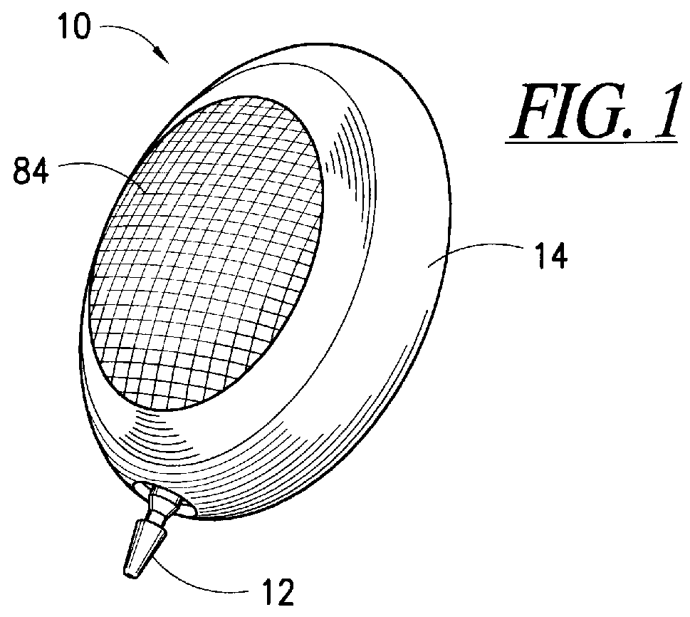
FIG. 1 is a perspective view of the injection port;

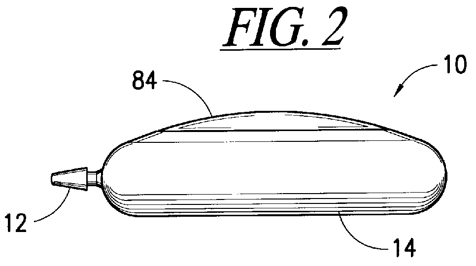
FIG. 2 is a side view of the injection port;

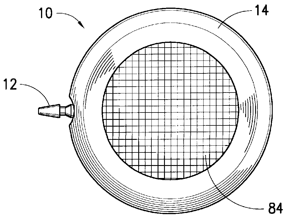
FIG. 3 is a top view of the injection port;

FIG. 4 is a cross-sectional view of the injection port;

FIG. 4a is a cross-sectional view similar to FIG. 4, without the needles and showing a decrease in residual volume via the solid disks;

FIG. 5 is a cross-sectional view of the injection port without the septum;

FIG. 6 is a top view of the housing partially broken away;

FIG. 7 is an exploded view of the septum assembly;

FIG. 8 is an exploded edge view of the disks;

FIG. 9 is a cross-sectional, enlarged view of the housing and connector during assembly; and

FIG. 10 is a cross-sectional, enlarged view of the housing and connector assembled with filter.

Apparatus and Method

The inventive injection port 10 and connector 12 attachment are shown in FIGS. 1 to 10. FIGS. 1-3 show the general appearance of the injection port 10 a...


PUM


Abstract

An implantable injection port consists of a very low profile housing with virtually no residual volume while maintaining a large target area for the needle.

Description

1. Field of the InventionThis invention relates to an implantable injector port and connector for use with an implantable catheter, for delivery of medications or nutrients to the vascular system or for blood sampling.2. Description of the Related ArtImplantable injection ports are provided under the patient's skin and receive medication infused through a patient's skin via a hypodermic needle. The injection ports provide a resealable septum and a housing to temporarily hold the medication before it proceeds via a catheter to the selected site in the patient. Montaivo, U.S. Pat. No. 5,476,460 teaches an infusion port with a substantially reduced internal volume through the use of inert beads which substantially fill the housing chamber. Low profile injection ports are also described in Cone et al., U.S. Pat. No. 5,108,377.None of the prior art injection ports provide a port that provides a low profile, a large septum that can withstand high operating pressures, a housing connector a...

Claims


Application Information

Patent Timeline
Patent Type & Authority Patents(United States)
IPC IPC(8): A61M39/02
CPCA61M39/0208
Inventor FOGARTY, TERENCE M.ARP, ROBERT A.
Owner FOGARTY TERENCE M
Why Eureka
Try Eureka