Draining gutter

a technology of draining gutters and gutters, which is applied in the direction of sewerage structures, valve details, instruments, etc., can solve the problems of affecting the growth of bacteria, mould and fungus, and the condition of moisture penetration into the frame of the building, and achieves the effect of reducing the number of problems, preventing the growth of bacteria, mould and fungus, and preventing the growth of mold and fungus

Inactive Publication Date: 2000-07-11
ERIKSSON BERTIL
View PDF10 Cites 14 Cited by
  • Summary
  • Abstract
  • Description
  • Claims
  • Application Information

AI Technical Summary

Benefits of technology

According to another preferred embodiment of the invention said arrangement comprises means adapted to be influenced by flows of media through the draining gutter for adjusting the air flow resistance of the channel means in dependence upon this influence. A draining gutter being self-regulated to a certain extent may in this way be provided as exhaust air means. This may for example be utilised so as to reduce the air flow resistance of the channel means upon a strong flow of water down into the draining gutter for maintaining a good air ventilation therein. But a possibility to regulate the waterflow through the draining gutter is primarily obtained, which is particularly advantageous when using the draining gutter as floor fire cock, since the water coming "the back way" may reduce the air flow resistance and by that also the resistance to the waterflow.
According to another preferred embodiment of the invention the draining gutter comprises a gutter member for receiving fluids, such as water, intended to be arranged in a hole in a floor and immersed with respect to the surrounding floor and connectable to the draining conduit, said arrangement comprises a body arranged in the gutter member for forming an obstacle against a flow of medium between an upper opening of the hole in the floor and the draining conduit therethrough, and a body is movably arranged with respect to the gutter member and adjustable with respect thereto for changing the air flow resistance of the channel means. An arrangement of such a body for adjusting the air flow resistance of the channel means is advantageous, since it enables a simple adjustment of the air flow resistance by displacing the body with respect to the gutter member.
According to another preferred embodiment of the invention the gutter member has inner walls converging downwardly, and the body is received inside the gutter member and has outer walls converging downwardly and arranged at a distance from said inner walls so as to form a passage for flow of air and fluid therebetween. For such a design of the gutter member and the body the air flow resistance of the channel means may easily be changed.

Problems solved by technology

It is in general also so that the environment as such in the room, such as for example a shower-room or a bathroom, in which the draining gutter is located has an unhealthy high humidity and results in exactly said draw-backs for people staying there as well as a risk that moisture penetrates into the frame of the building and gives rise to rot or other damaging effects.
Thus, it gets possible to obtain a ventilation of the space in question through the draining gutter, which by this gets a double function, and thanks to the conduction of air therethrough it become possible to keep the humidity level in the draining gutter as well as in the draining conduit at such a low level that the conditions for growth of bacteria, mould and fungus gets very bad and the problems connected thereto disappear.

Method used


Image

  • Draining gutter
  • Draining gutter
  • Draining gutter

Examples


Embodiment Construction

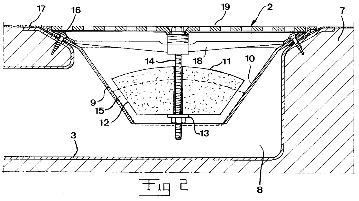
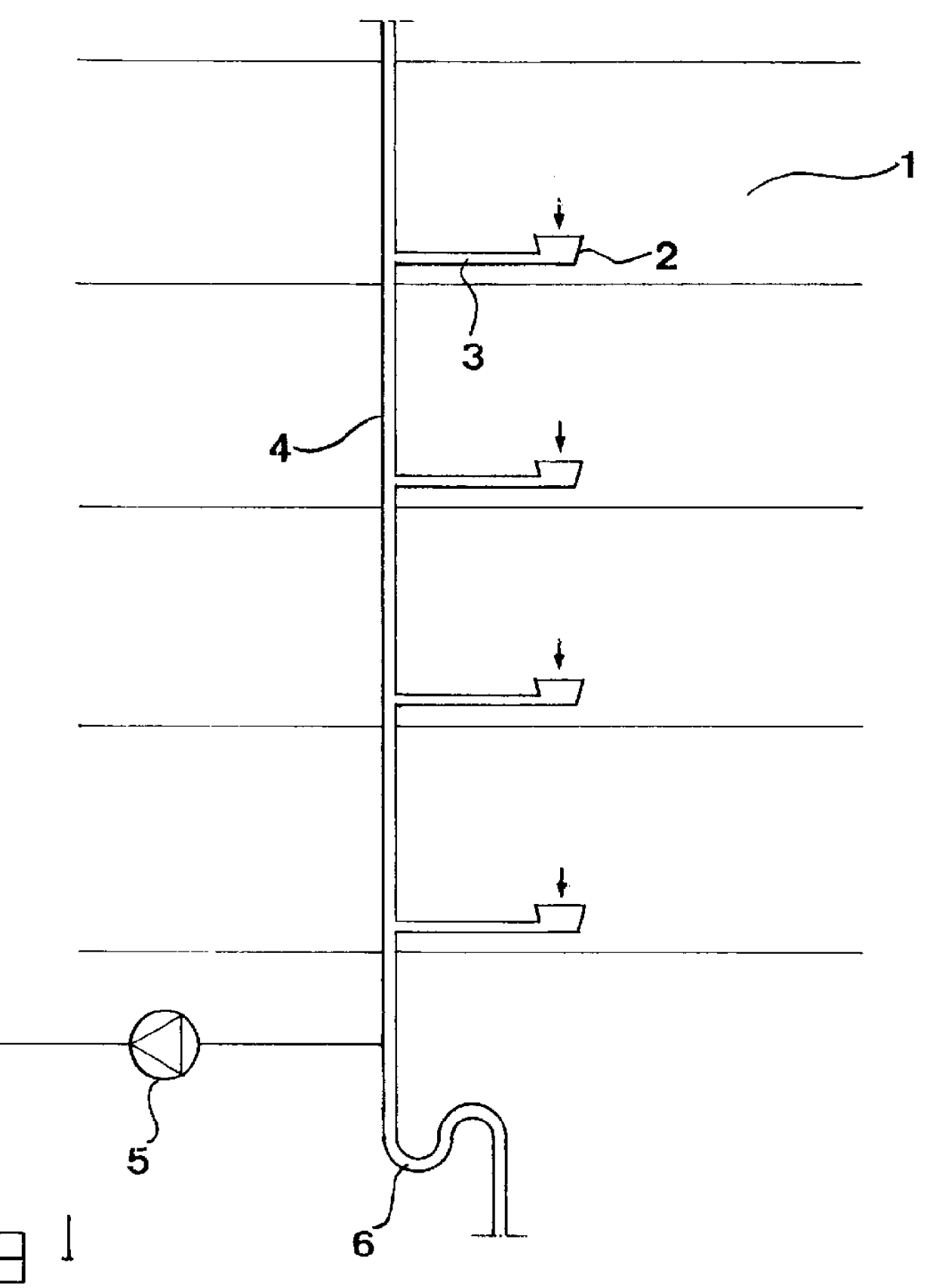
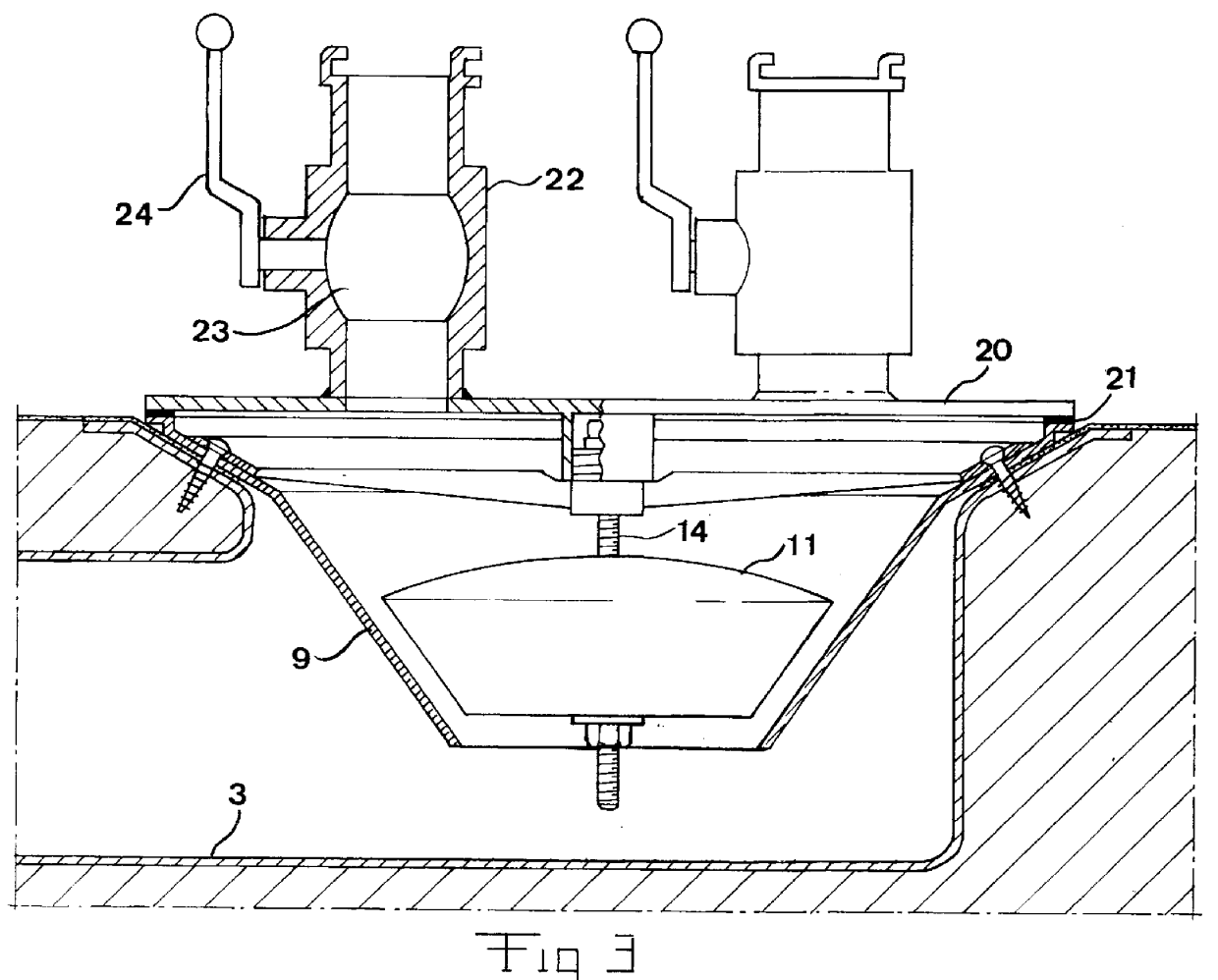
A part of a draining system in a building having several floors is schematically illustrated in FIG. 1, in which for the purpose of simplicity only draining gutters 2 arranged in different spaces or rooms 1 have been illustrated as units receiving water in the draining system. It is illustrated how these draining gutters are connected to a respective draining conduit 3, which in its turn is connected to a draining conduit 4 in common, to which a fan 5 is connected for generating a flow of air from the respective space through a draining gutter, the draining conduit 3, the draining conduit 4 in common and out at the exhaust side of the fan, which could be connected to the open air, but it is preferably connected to any heat exchanger for taking care of the heat contained in the air from the spaces. Preferably, other units receiving drain water, at least toilets, are in a case like this connected to another draining conduit in common than the conduit 4. Furthermore, the draining condu...


PUM


Abstract

PCT No. PCT / SE97 / 01808 Sec. 371 Date Apr. 29, 1999 Sec. 102(e) Date Apr. 29, 1999 PCT Filed Oct. 29, 1997 PCT Pub. No. WO98 / 19021 PCT Pub. Date May 7, 1998A draining gutter, which is adapted to be placed in a floor of a space inside a building for conducting drain water away from the space through a draining conduit (3) connected thereto, has channel (15) adapted to conduct air from the space to the draining conduit upon influence of air present in the conduit away from the space. The draining gutter has also an arrangement (11, 13, 14) for adjusting the air flow resistance of the channel.

Description

FIELD OF THE INVENTION AND PRIOR ARTThe present invention relates to a draining gutter adapted to be placed in a floor of a space inside a building for conducting drain water away from the space through a draining conduit connected thereto.Such draining gutters are arranged in different types of sanitary spaces or rooms, such as for example bathrooms and shower-rooms, so as to receive and transport water, such as bathwater and showerwater, away. However, they may also be placed in other spaces where it is conceivable that it is desired to transport water or any other liquid resulting from for example any type of process from the space, such as any type of laboratory, work-shop premises or the like. Although water is discussed here and in the claims, this is not at all to be interpreted as limiting the invention, but there is mostly a question about water, and water is here defined as comprising all types of fluids.In order to illuminate but not in any way restrict the invention the ...

Claims


Application Information

Patent Timeline
Patent Type & Authority Patents(United States)
IPC IPC(8): E03F5/04
CPCE03F5/0408E03F2005/0413E03F2005/0416E03F2005/0417Y10T137/7436Y10T137/085Y10T137/6988
Inventor ERIKSSON, BERTIL
Owner ERIKSSON BERTIL
Why Eureka
Try Eureka