

Voltage translator circuit which allows for variable low voltage signal translation
a translator circuit and low voltage technology, applied in logic circuits, logic circuit coupling/interface arrangements, pulse techniques, etc., can solve the problems of fixed voltage on the low voltage side of the translator, or at best, voltage limitation
- Summary
- Abstract
- Description
- Claims
- Application Information
AI Technical Summary
Benefits of technology
Problems solved by technology
Method used
Image

Examples
Embodiment Construction
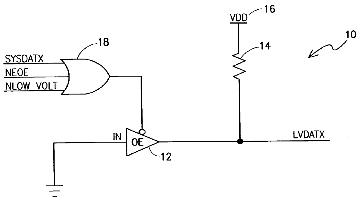
In accordance with one embodiment of the present invention, a variable low voltage signal translator is disclosed. The variable low voltage signal translator has a driver circuit. A control circuit is coupled to the driver circuit and is used for enabling and disabling the driver. The control circuit has at least one input coupled to a signal that the signal translator is to translate. A resistor has one terminal coupled to an output of the driver circuit and a second terminal coupled to a voltage supply. The voltage supply is used to supply the low voltage level of the variable low voltage signal translator.
In accordance with one embodiment of the present invention, a variable low voltage signal translator for a data bus is disclosed. The variable low voltage signal translator for a data bus uses a driver for outputting a low voltage signal translation of data on said data bus. A control circuit is coupled to the driver for enabling and disabling the driver. The control circuit has...
PUM
 Abstract
Description
Claims
Application Information