Image display system

a technology of image display and display screen, applied in the field of image display system, can solve problems such as uneconomical system construction

Inactive Publication Date: 2001-12-18
OLYMPUS OPTICAL CO LTD
View PDF8 Cites 93 Cited by
  • Summary
  • Abstract
  • Description
  • Claims
  • Application Information

AI Technical Summary

Benefits of technology

It is another object of the present invention to provide an image display system capable of adapting the number of the HMDs easily, and capable of constructing the image display system economically in the case of individual use.
According to the present invention, the controller of the plural image display units each having the controller and at least one display means is connected in series to one external control device through the external control terminal and the output terminal of respective controllers, so that the external control device may control collectively and forcibly the operation modes of whole display means through respective controllers, and thus may correspond easily to the number of the image display units, that is, the number of display means. Also, it is not necessary for the controller itself of respective image display units to have a function of forcibly controlling the operation modes of the display means externally, so that the system construction of respective image display units may be made cheap.

Problems solved by technology

However, such forcible control circuits or the like are efficient in the case of using a plurality of HMDs, but these circuits are not necessary in the case of using only one HMD, so that in such only one HMD utilization, the system construction becomes uneconomical.

Method used


Image

  • Image display system
  • Image display system
  • Image display system

Examples


first embodiment

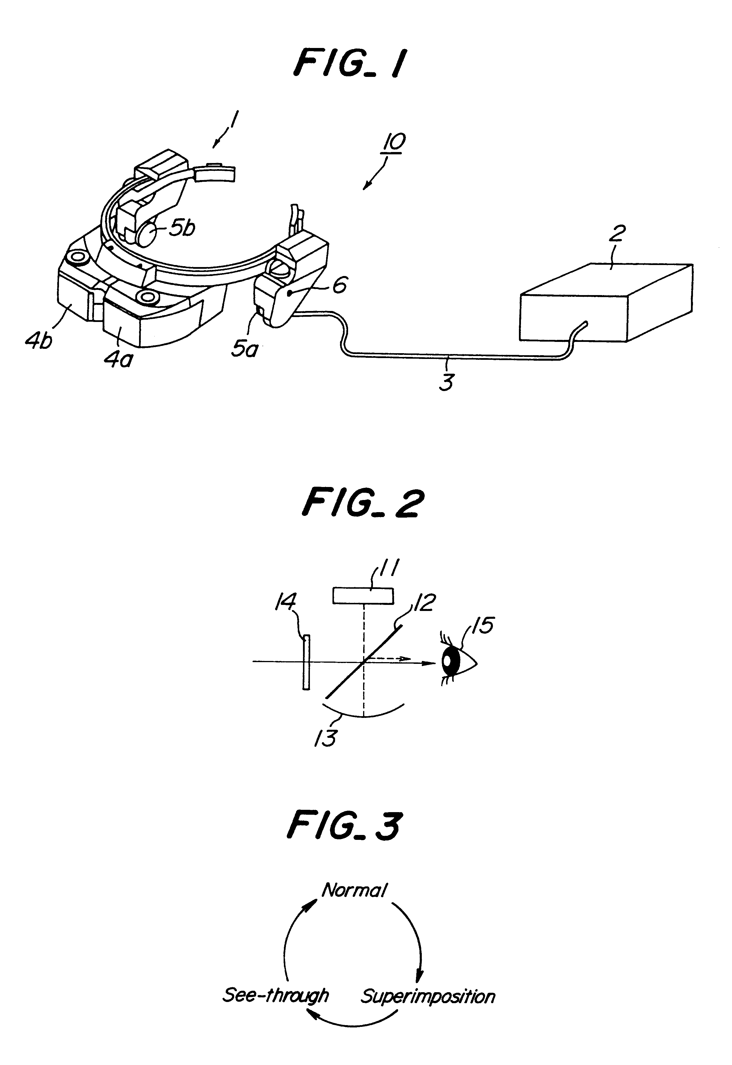
FIG. 1 is an perspective view showing a construction of one embodiment of an image display unit used in an image display system according to the present invention. The image display unit 10 comprises an HMD 1 constructing at least one display means, a controller 2 for controlling the operation modes of the HMD 1, and a cable 3 for connecting these HMDs and the controller. The HMD 1 comprises right and left projection optical systems 4a, 4b, right and left ear-phones 5a, 5b and a switch 6 for switching the operation modes. The controller 2 also comprises circuits for supplying required power, image signal and voice signals or the like to the HMD 1 through the cable 3, and a mode switching unit. The controller 2 also includes an external control terminal for receiving mode control signals from an external control device described later and an output terminal for outputting the mode control signals inputted from the external control device. The HMD 1 or the controller 2 is provided wit...

fifth embodiment

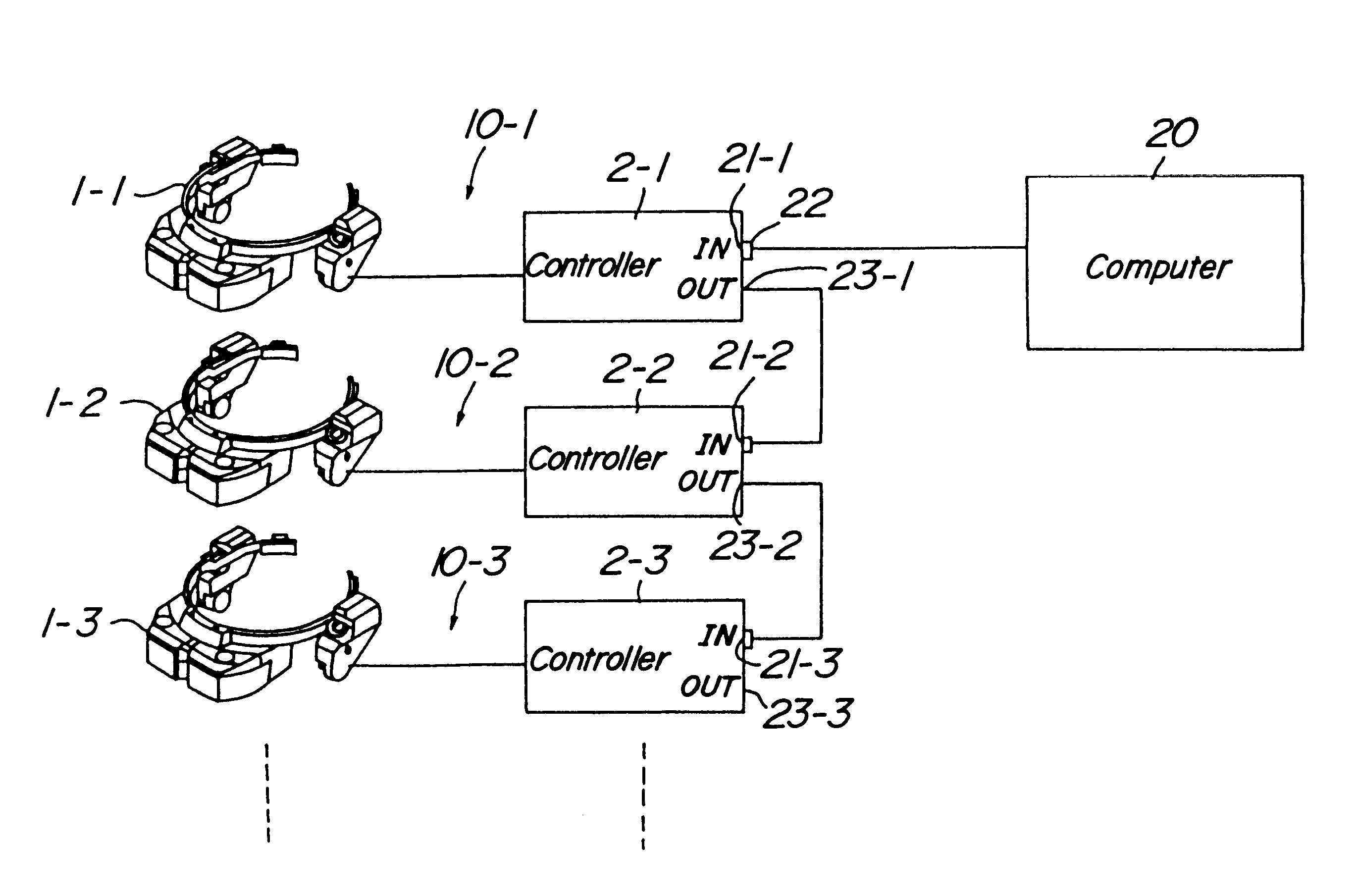
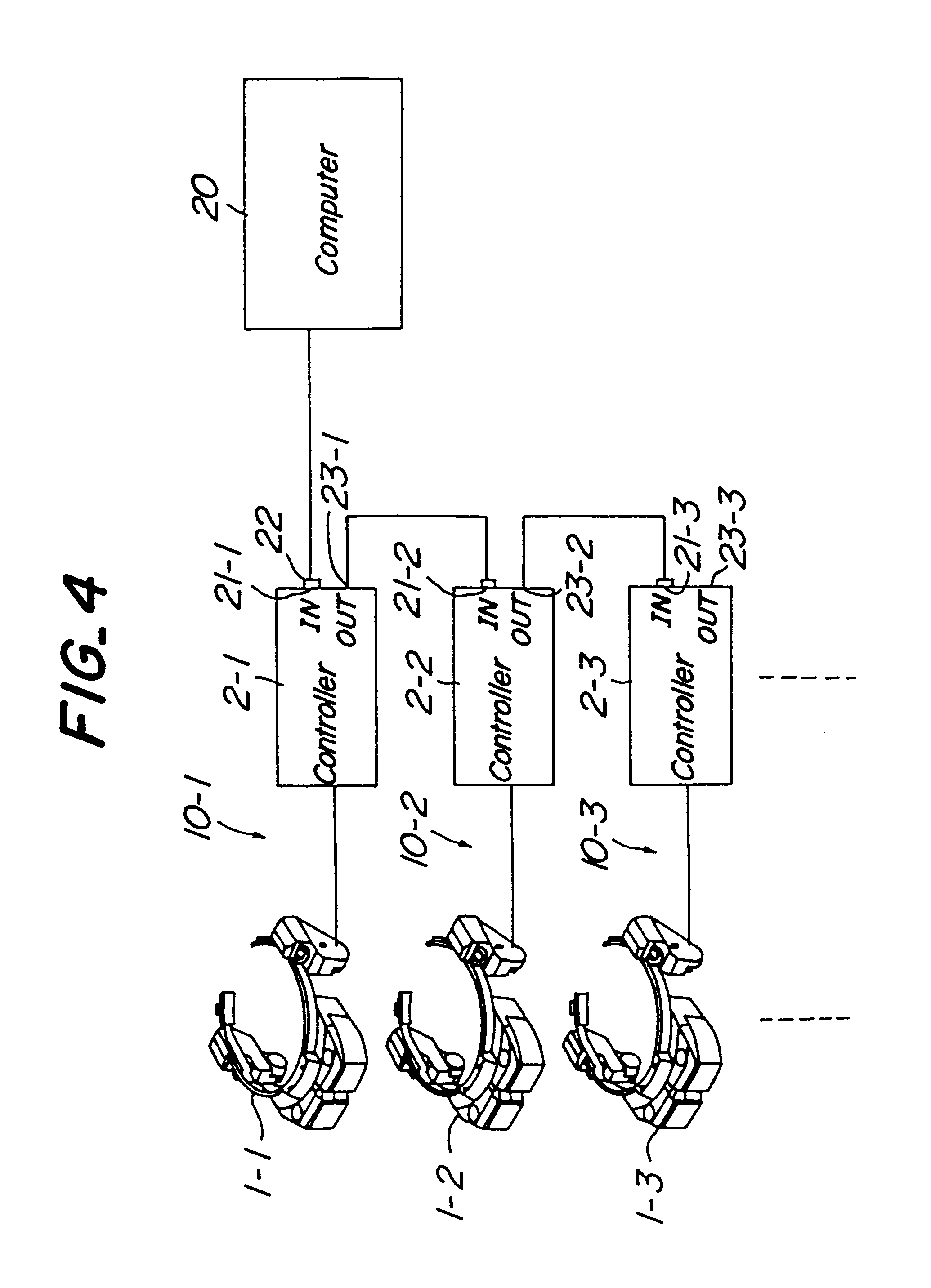
FIG. 10 shows the image display system according to the present invention. In this embodiment, a plurality of image display units 10 shown in FIG. 1 are coupled in series to form the plural (in this embodiment, two) image display unit groups 40-1, 40-2, these image display unit groups 40-1, 40-2 are connected to one computer 20 in parallel, so that the computer 20 performs different mode control between different image display unit groups and collective control in the same image display unit group. In this embodiment, also, all HMDs 1 may be switched forcibly and collectively to the see-through operation mode.

It is further understood by those skilled in the art that the present invention is not limited to only the above described embodiments and that various changes and modifications may be made in the invention without departing from the spirit and the scope thereof. For example, in the first embodiment, the remote controller 30 can be used instead of the computer 20 in the same ma...


PUM


Abstract

An image display system for viewing an electronic image and an external sight simultaneously, which includes image display units which have an individual controller for outputting image signals to a display unit. The display unit enables a switching operation with a predetermined operation mode from a plurality of operation modes, including a mode for indicating the image signals output from the individual controller. An external control device outputs mode control signals which address the operation mode of the display unit and are received by an external control terminal. A mode exchanging switch specifies a condition of the mode control signal. A detection unit detects whether the external control terminal is connected to a connector capable of outputting a mode control signal. The individual controllers are connected to the external control terminals in turn so as to couple the controllers to the external control device in series. The operation modes can be collectively and forcibly controlled by the individual controllers on the basis of mode control signals received by the external control unit.

Description

1. Field of the InventionThe present invention related to an image display system capable of viewing an electronic image and an external sight simultaneously, or selectively.2. Related Art StatementHitherto, there has been provided a head mounted display (hereinafter, referred to as an HMD) having for example a see-through function capable of viewing not only an electronic image, but also an external sight (for example, refer to Japanese Patent Application Opened Nos. 281,891 / 90 and 26,289 / 92).For example, Japanese Utility Model Application No. 52,288 / 94 discloses an image display system in which a plurality of see-through HMDs can be connected to a controller for outputting image signals, a third party other than a viewer can control through the controller one operation mode which renders a given electronic image viewable to all viewers or an other operation mode which renders an external sight viewable to all viewers.According to such an image display system, there is an advantage...

Claims


Application Information

Patent Timeline
Patent Type & Authority Patents(United States)
IPC IPC(8): G02B27/01G06F3/147G09G3/00H04N5/64
CPCG02B27/017G06F3/147G09G3/001
Inventor TOKUHASHI, YUKISHIMADA, NAOTO
Owner OLYMPUS OPTICAL CO LTD
Why Eureka
Try Eureka