Muscle stimulating device and method for diagnosing and treating a breathing disorder

a muscle stimulating device and breathing disorder technology, applied in the direction of artificial respiration, diagnosis recording/measuring, therapy, etc., can solve the problems of hypersomnolent sleep apnea patients at risk for excessive mortality, sleep fragmentation and complete or near cessation, and severe degrees of oxyhemoglobin desaturation

Inactive Publication Date: 2004-08-03
RIC INVESTMENTS LLC
View PDF47 Cites 223 Cited by
  • Summary
  • Abstract
  • Description
  • Claims
  • Application Information

AI Technical Summary

Benefits of technology

It is a further object of the present invention to minimize the heat experienced by the patient as a result of using the magnetic stimulator. To that end, the present invention includes an insulating material between the patient's skin and the coil. In addition, the temperature of the coil is monitored by a temperature sensor and the power to the coil is controlled based on the temperature of the coil so that excessive heat is not generated in the coil. Also, portions of the coil are maintained as far from the patient as possible while still permitting the magnetic stimulator to provide its therapeutic effect.
It is a still further object of the present invention to control the application of magnetic energy to the patient based on the condition of the patient. To achieve this object, sensors are provided to monitor the condition of the patient. For example, sensors are used to determine whether the patient is snoring and / or experiencing an apneic event. If so, the coil is energized to treat the OSA. Energizing the coil can also be synchronized with the patient's respiration so that stimulation begins within a predetermined window during the patient's respiratory cycle, such as at the onset of inspiration or at a period offset therefrom. Also, the present invention contemplates using the conditions of the patient, such as the presence of snoring, an apneic event and / or the respiratory patterns of the patient, to regulate the intensity of the magnetic stimulation. For example, the more prevalent the apneic events, the greater the level of stimulation. Conversely, a reduced number of apneic events results in a reduced level of stimulation. In this manner, only the necessary level of magnetic energy is applied to the patient.

Problems solved by technology

Those afflicted with OSA experience sleep fragmentation and complete or nearly complete cessation of ventilation intermittently during sleep with potentially severe degrees of oxyhemoglobin desaturation.
Hypersomnolent sleep apnea patients may be at risk for excessive mortality from these factors as well as by an elevated risk for accidents while driving and / or operating potentially dangerous equipment.
Neither of these therapies is successful in all cases.
On the other hand, the nasal mask needed to apply a positive air pressure is not tolerated by some OSA patients.
Pharmacological therapy has been, in general, less than satisfactory, and side effects are frequent.
Because these current densities are disposed at the surface of the patient, which also contains a relatively large number of nerve endings, such electrical stimulation devices can cause unpleasant or painful sensations, possibly arousing the user from sleep.
Thus, electrical stimulation using implanted electrodes reduces the likelihood that the electrical stimulation will induce an unpleasant or painful sensation in the patient.
However, electrical muscle stimulation utilizing implanted electrodes requires surgical intervention, the permanent presence of foreign materials within the patient's neck tissue, and at least one electrical connection protruding from the patient.
Consequently, there is a potential for infection or irritation at the surgical site and at the site where the electrode protrudes through the surface of the patient.

Method used


Image

  • Muscle stimulating device and method for diagnosing and treating a breathing disorder
  • Muscle stimulating device and method for diagnosing and treating a breathing disorder
  • Muscle stimulating device and method for diagnosing and treating a breathing disorder

Examples


first embodiment

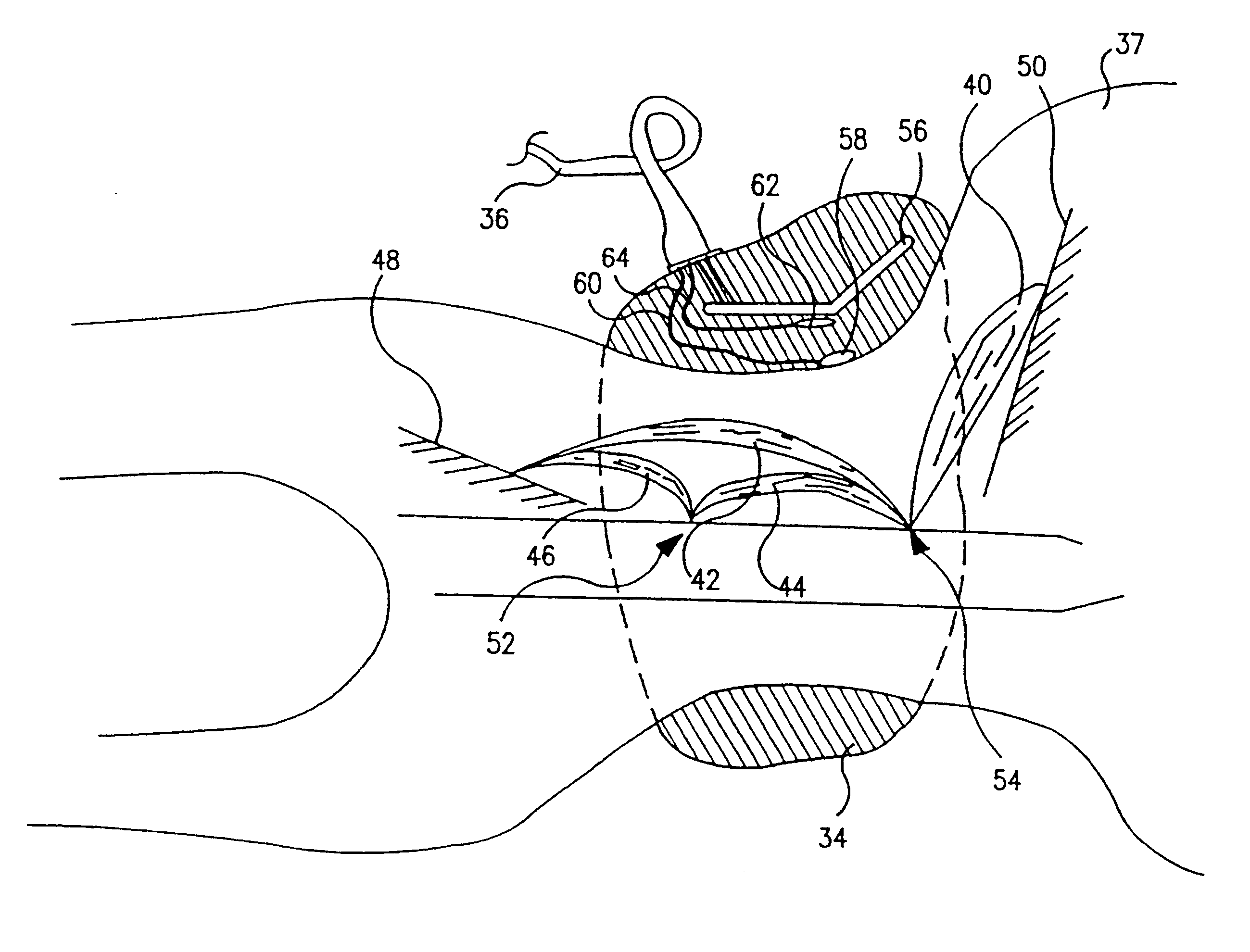
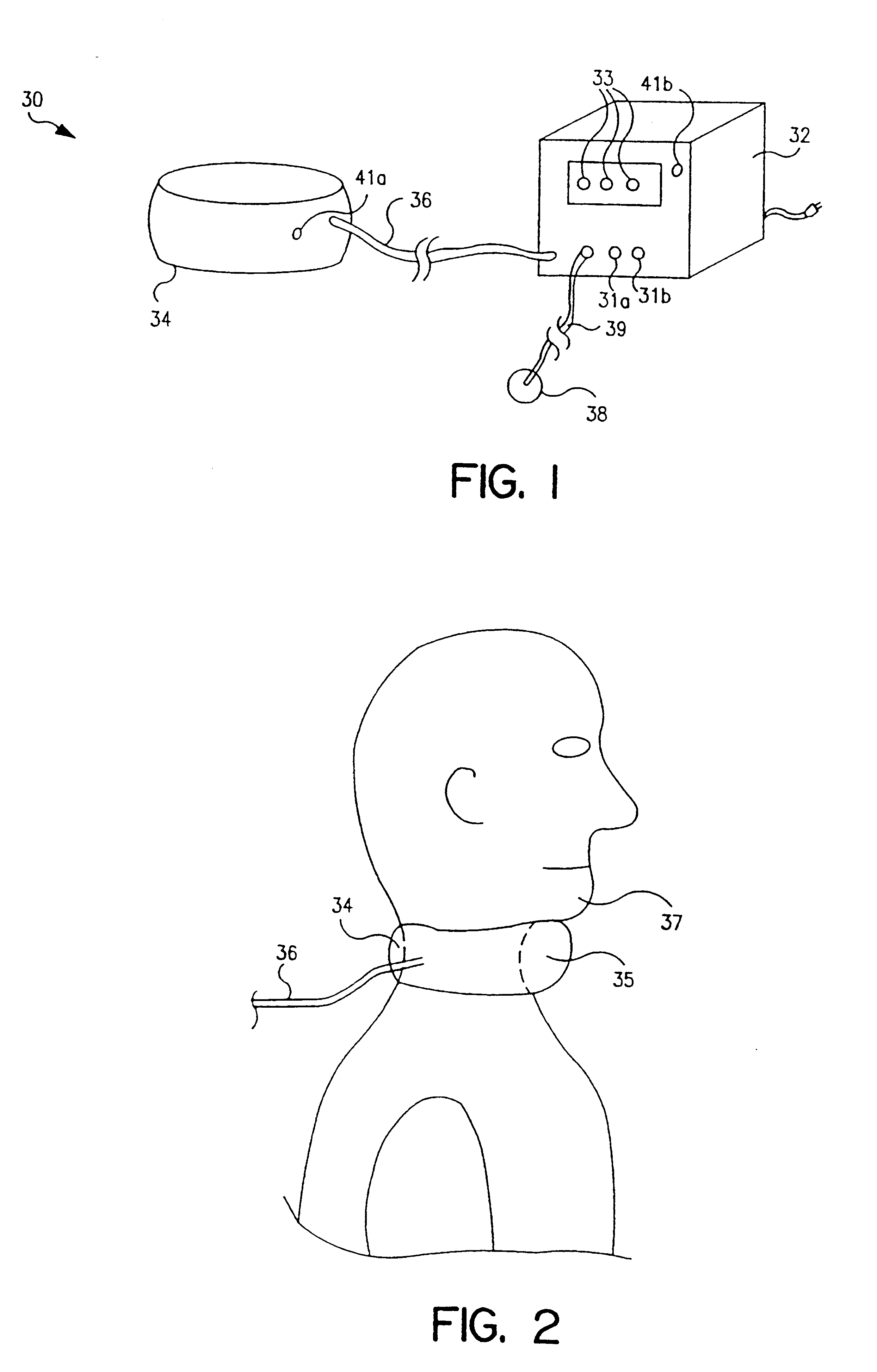
FIG. 1 illustrates a magnetic stimulator 30 according to the principles of the present invention. Magnetic stimulator 30 includes a control unit 32 and a collar 34 coupled to control unit 32 via a flexible cable 36. Collar 34 attaches to the patient's neck, as shown in FIG. 2, such that a portion 35 of collar 34 containing at least one magnetic field generating coil is disposed directly under the patient's chin 37. Control unit 32 receives signals from at least one sensor, such as sensor 38, which is connected to control unit 32 via a cable 39. Control unit 32 energizes the coil in collar 34 to produce a time varying electrical current that creates a changing magnetic field, whose rapidly increasing flux, in turn, creates a spacially varying electric field having a gradient that is maximized at specific muscles and / or muscle nerves in the upper airway. In short, the changing magnetic field produced by energizing the coil with a time varying current, such as a pulse train, induces te...

second embodiment

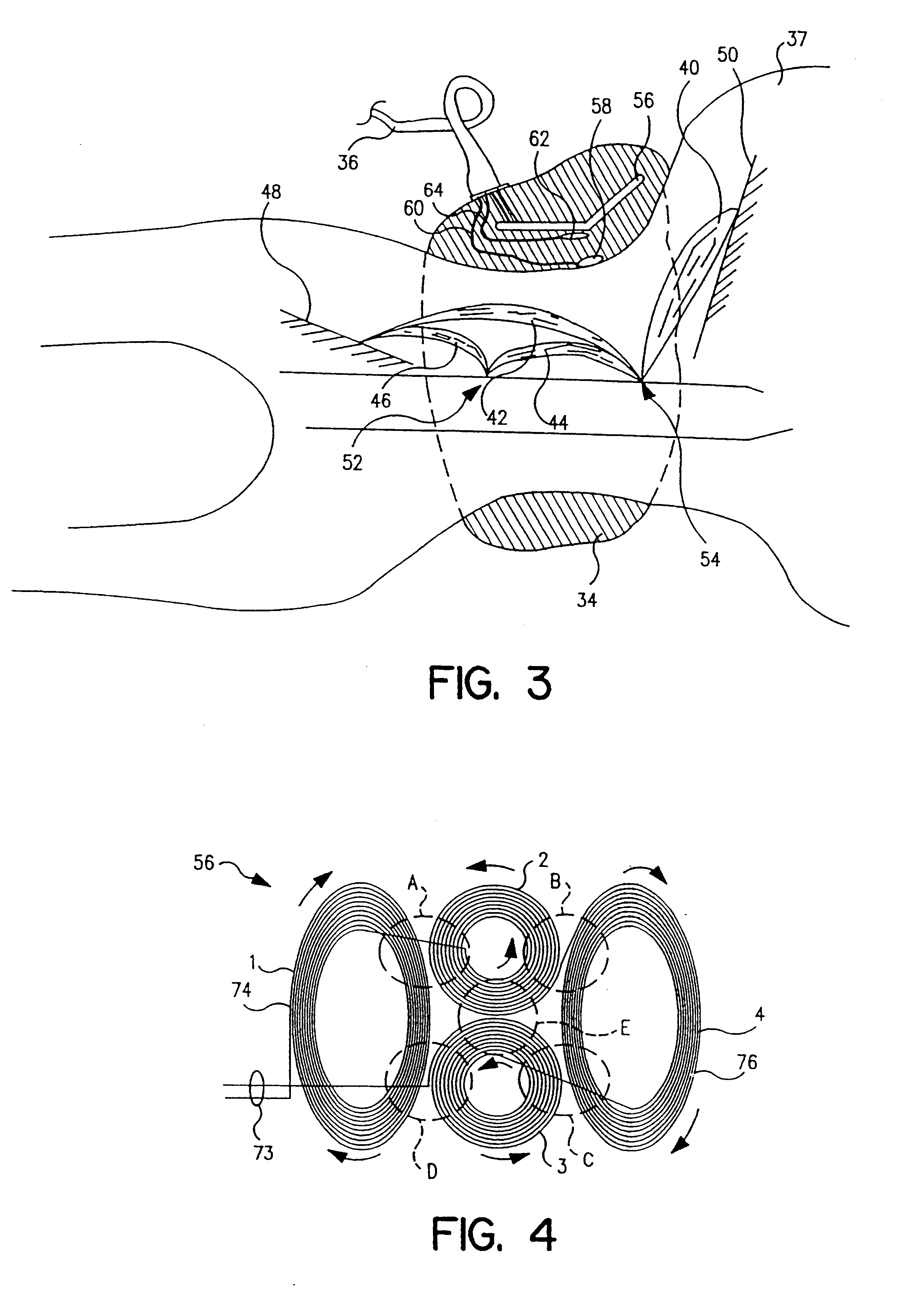
A second embodiment for the coil used in the collar according to the principles of the present invention is shown in FIG. 7A. In this embodiment, six generally similar loops 82, 84, 86, 88, 90 and 92 define coil 80 with a current passing therethrough as indicated by the arrows. In the illustrated embodiment, loops 82, 84, 86, 88, 90 and 92 have the same number of turns and are wound from a continuous electrical wire. Because the loops in coil 80 are connected in series, a single pair of terminals 94 are all that is required to energize the coil. The coil configuration illustrated in FIG. 7A provides generally the same magnetic field pattern as the coil configuration illustrated in FIGS. 4-6. Namely, four magnetic field concentrations of generally uniform magnitudes are provided generally at areas A, B, C and D when a current is provided to terminal 94.

As noted above, the plurality of loops in coil 56 of FIG. 4 and in coil 80 of FIG. 7A are defined from a continuous wire so that only...

third embodiment

As with the previous embodiments, four areas of increased magnetic field concentrations A-D are created by energizing loops 83a-83c and 85a-85c. Loops 83a, 83b and 83c have a common terminal 87, and loops 85a, 85b and 85c have a common terminal 89. As noted above, terminals 87 and 89 can be connected to separate power supplies, i.e., driven by separate currents, so that each group of loops is energized independently of the other, both in terms of timing and magnitude. Alternatively, terminals 87 and 89 can be connected together so that each group of loops receives the same current. This third embodiment of the coil simplifies the manufacture of the coil by enabling each group of loops to be made individually and combined to define the coil, thereby avoiding the relatively complicated winding pattern required to manufacture the coil illustrated in FIGS. 4 and 7A.


PUM


Abstract

A device and method for magnetic stimulation of muscles for the diagnosis and relief of a breathing disorder, such as obstructive sleep apnea is disclosed. Magnetic stimulation is used to stimulate muscles which serve to stabilize the upper airway of an individual whose nocturnal apneic events are related to diminished muscle tone. A sensor monitors a physiologic characteristic of the patient, a coil is energized to stimulate the appropriate muscles associated with the upper airway, a power supply provides power for energizing the coil, and a control system controls the application of power to the coil based on the output of the sensor. Diagnosis of obstructive sleep apnea is accomplished by measuring the subject's compliance in the presence and absence of the magnetic stimulation of the upper airway muscles. The smaller the difference between these two compliance levels, the more likely that patient suffers from obstructive sleep apnea.

Description

1. Field of the InventionThe present invention pertains to an apparatus and method for noninvasive stimulation of muscles in the upper airway to diagnose and / or treat a breathing disorder, such as obstructive sleep apnea. In particular, the present invention pertains to a magnetic stimulation device and a method of using the device to apply pulsed magnetic fields to the muscles in the neck area of a patient to induce tension in such muscles, thereby relieving the obstructive sleep apnea caused by a relaxation of such muscles. By measuring an awake patient's compliance in the presence and absence of the magnetic stimulation, the likelihood that the patient suffers from obstructive sleep apnea can be determined.2. Description of the Related ArtObstructive sleep apnea (OSA) is a condition in which sleep is repeatedly interrupted by an inability to breathe due to an obstructed upper airway segment. Those afflicted with OSA experience sleep fragmentation and complete or nearly complete c...

Claims


Application Information

Patent Timeline
Patent Type & Authority Patents(United States)
IPC IPC(8): A61N2/02A61N2/00A61N2/04
CPCA61N2/006A61N2/02
Inventor MECHLENBURG, DOUGLAS M.GAUMOND, ROGER PAUL
Owner RIC INVESTMENTS LLC
Why Eureka
Try Eureka