Fiber jumpers with data storage method and apparatus

Inactive Publication Date: 2004-10-26
AMERICAN TELEPHONE & TELEGRAPH CO
View PDF9 Cites 246 Cited by
  • Summary
  • Abstract
  • Description
  • Claims
  • Application Information

AI Technical Summary

Problems solved by technology

Labeling the fiber jumpers is a critical task because with so many jumpers located in a bay, it is easy to make a mistake and connect the jumpers to the wrong receptacle in the bay.
This would have disastrous consequences since the jumpers connect communications end-points.
Connecting the wr

Method used


Image

  • Fiber jumpers with data storage method and apparatus
  • Fiber jumpers with data storage method and apparatus
  • Fiber jumpers with data storage method and apparatus

Examples


Embodiment Construction

While the present invention is described herein with reference to illustrative embodiments for particular applications, it should be understood that the invention is not limited thereto. Those having ordinary skill in the art and access to the teachings provided herein will recognize additional modifications, applications, and embodiments within the scope thereof and additional fields in which the present invention would be of significant utility.

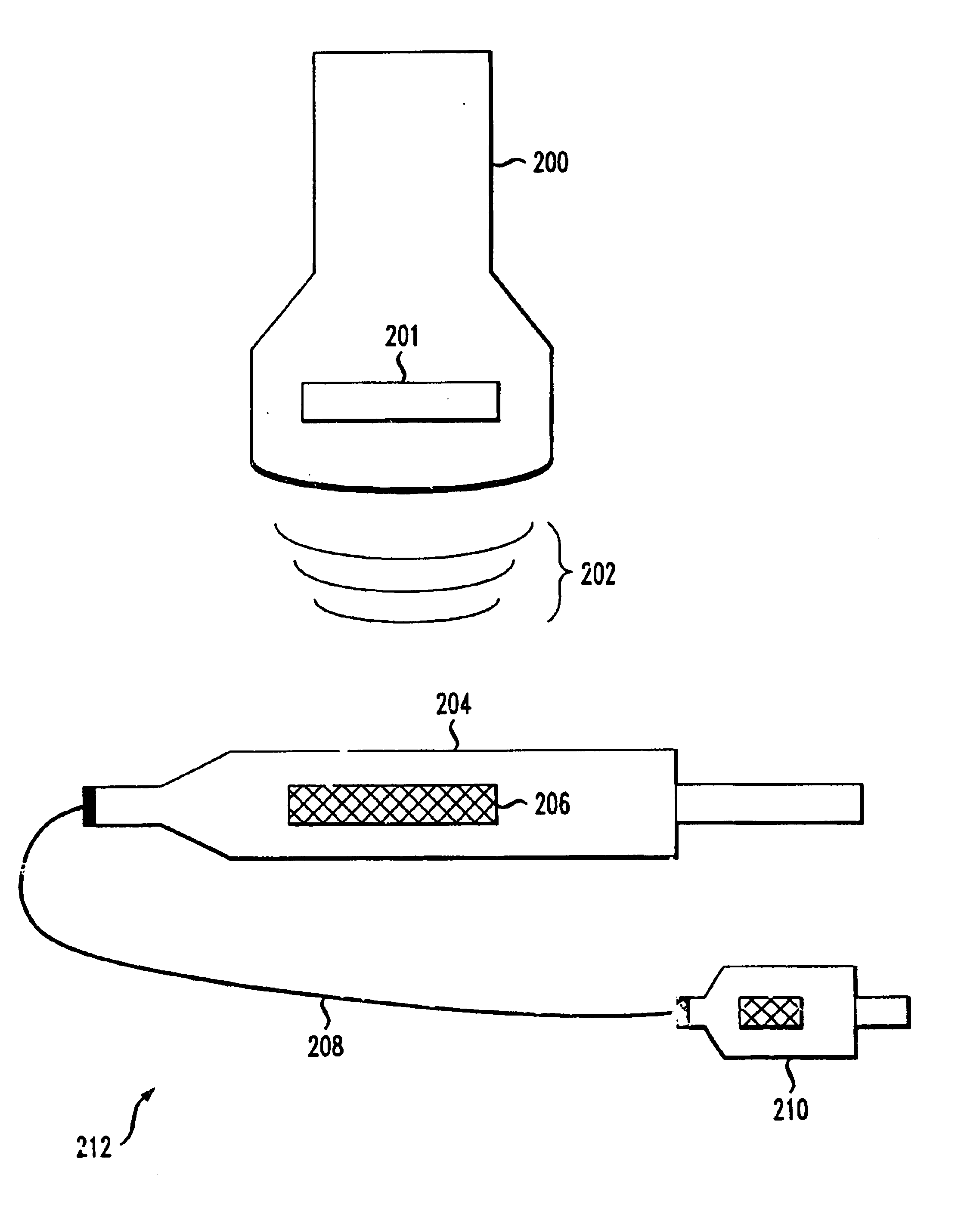
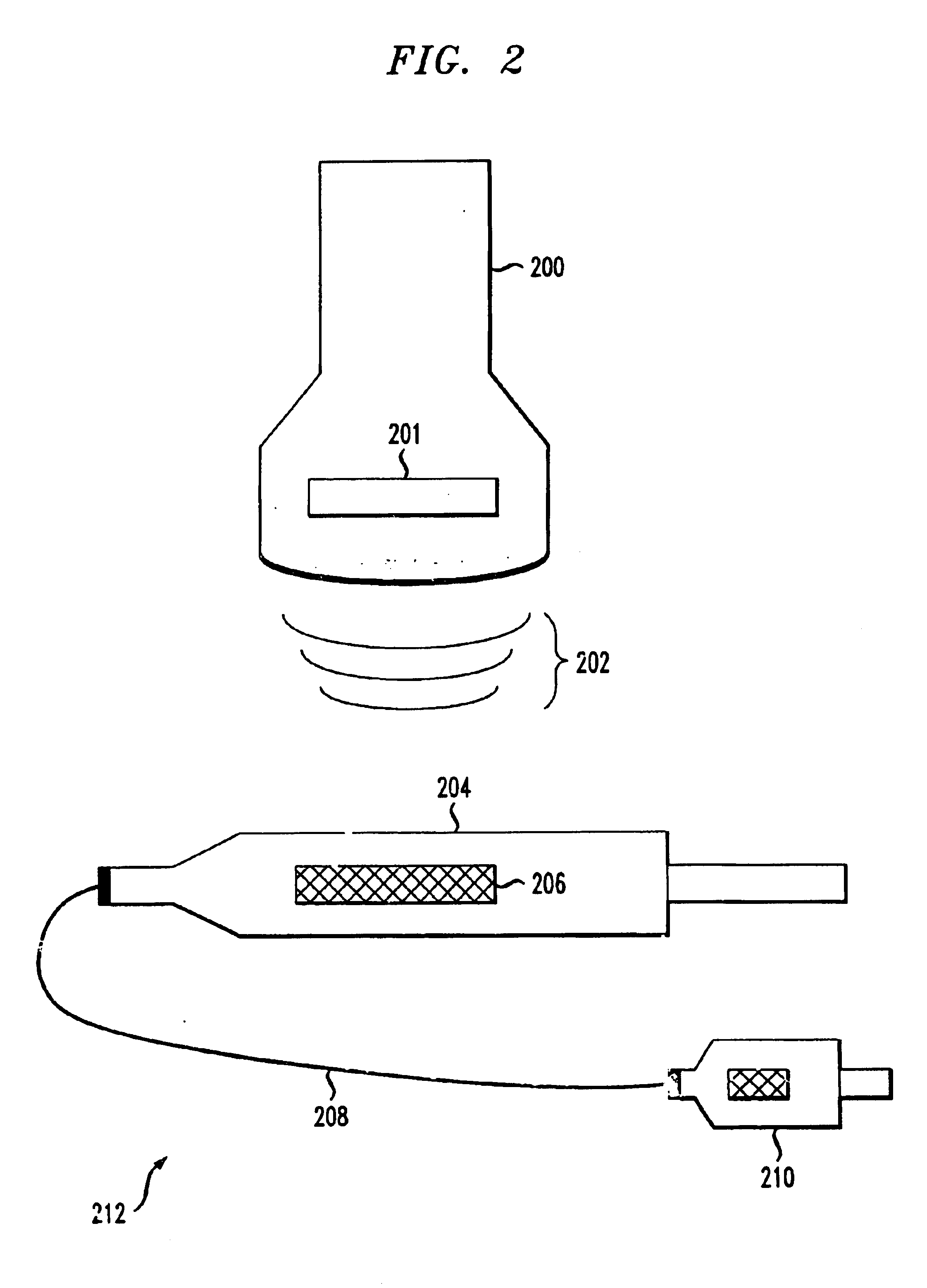
In one embodiment of the present Invention, a method and apparatus of identifying and managing jumper cables, such as fiber jumper cables, is presented. Fiber cables are terminated in bays. Fiber cables connect communications electronics, which may also be located in the bay. Fiber jumper cables are used to connect (e.g. patch) the fiber cables to the communications electronics.

A fiber jumper includes a fiber pair, with a connector on each end. Fiber jumpers implemented in accordance with the teachings of the present invention may include S...


PUM


Abstract

A method and apparatus for identifying fiber optic jumper cables is presented. A radio-frequency identification system is presented in which a tag is placed in an ST connector. The tag includes a memory storing jumper cable identification information. The jumper cable identification information identifies the jumper cable. A radiating unit radiates the tag with electromagnetic waves and the tag is energized. Once energized, the tag communicates the jumper cable identification information located in the memory to the radiating unit. The radiating unit then displays the jumper cable identification information. As such, a technician is able to identify a jumper associated with the connector and connect the jumper to an appropriate communications bay.

Description

1. Field of the InventionThis invention relates to infrastructure. Specifically, the present invention relates to cable infrastructure.2. Description of the Related ArtModern communications systems include electronics linked by wired connections and wireless connections. Wired communications links are typically implemented with cabling such as twisted pair cabling, coaxial cabling and fiber-optic cabling. The cabling is run between end electronics to facilitate the communication of information.Fiber-optic cabling has become the medium of choice for use on communications links. Fiber-optic cabling typically facilitates faster, higher bandwidth communications. A fiber-optic communications link may be implemented with two fibers, one for transmit signals and a second for receive signals. Since the fiber-optic cable accomplishes communications with light, special termination devices (e.g. connectors) are fused at the end of the cable to connect the cable to termination equipment (e.g. c...

Claims


Application Information

Patent Timeline
IPC IPC(8): G06K19/06G01S13/82
CPCG01S13/825G02B6/3895H04Q1/149G02B6/4452
Inventor ESLAMBOLCHI, HOSSEINHUFFMAN, JOHN SINCLAIR
Owner AMERICAN TELEPHONE & TELEGRAPH CO
Why Eureka
Try Eureka