

Food basting device
- Summary
- Abstract
- Description
- Claims
- Application Information
AI Technical Summary
Benefits of technology
Problems solved by technology
Method used
Image

Examples
Embodiment Construction
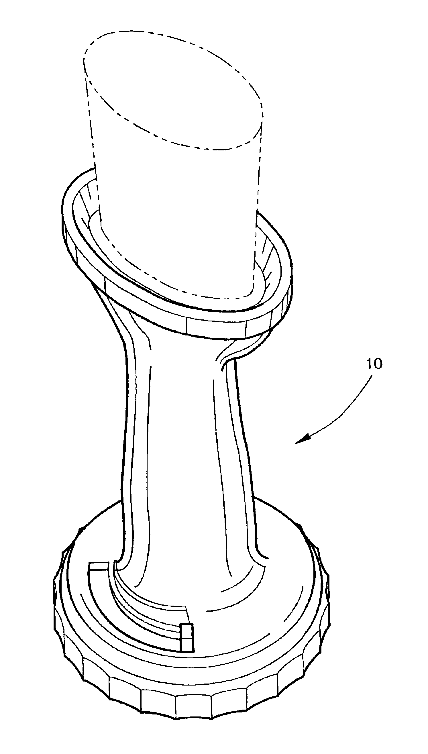
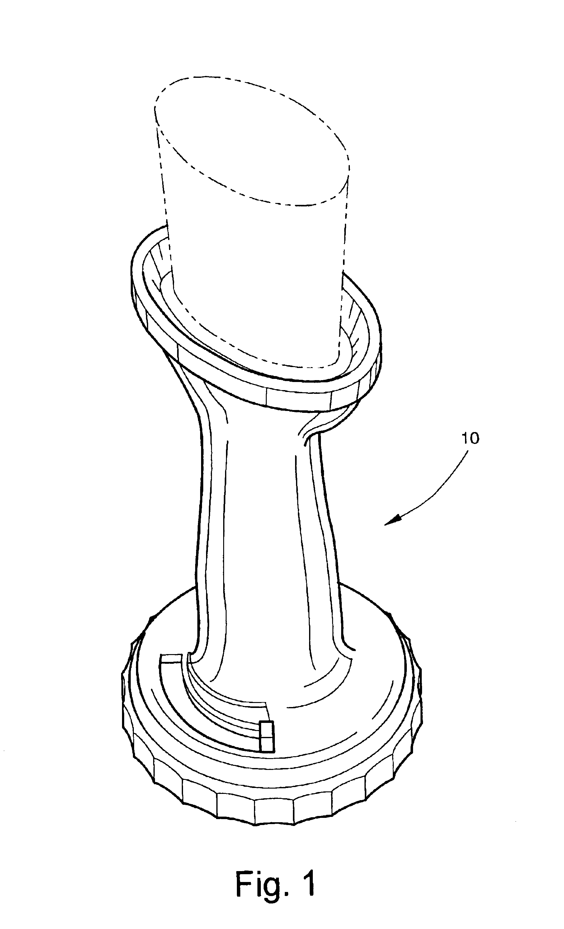
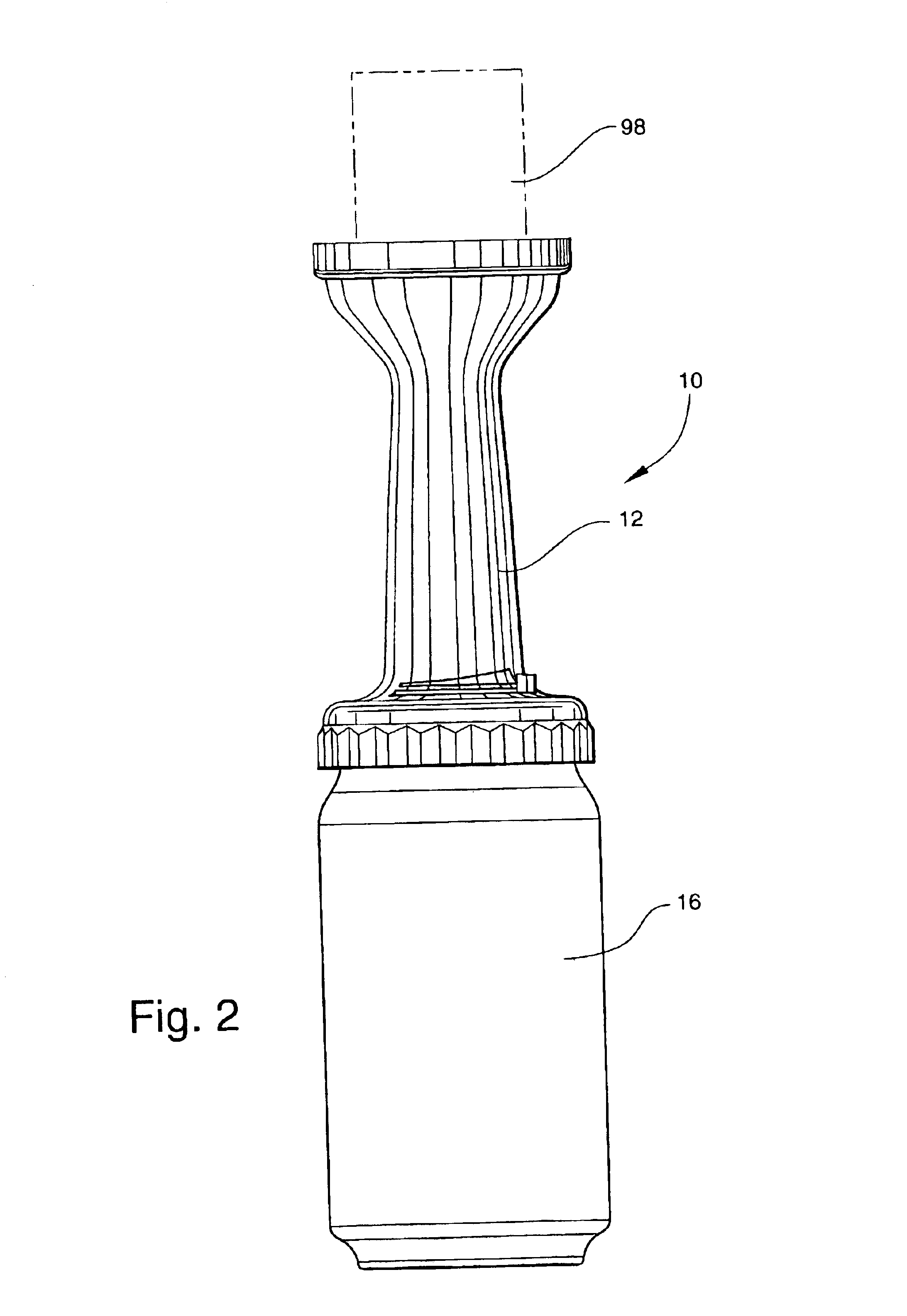
The present invention is a device that is useful for basting food products in the cooking process. More specifically, the present invention is a device that is useful by providing variable fluid flow capabilities to food product basting appliances.
Referring now to FIGS. 1-7, the present invention is a food basting device and is generally represented as 10. The food basting device 10 comprises two primary pieces, a brush piece 12 and a flow regulating piece 14 (the brush may be either integrally molded onto the brush piece 12 or separately attached as illustrated in FIG. 5).
The brush piece 12 of the present invention is designed to work in combination with a fluid container 16. The preferred form of fluid container 16 would be one without screw threading for caps and lids. The most preferred form is a beverage type container, such as a beer or soda type container.
The brush piece 12 comprises a cylindrical portion 22 with a circular disk portion 24 that forms a top for the cylindrical...
PUM
 Abstract
Description
Claims
Application Information