Autonomous floor-cleaning robot

a robot and floor cleaning technology, applied in the direction of cleaning action control, instruments, applications, etc., can solve the problems of reducing the service life reducing the efficiency reducing the use value of the cleaning robot, so as to minimize the power requirements of the cleaning mechanism and optimize the cleaning capability and efficiency of the cleaning mechanism.

Inactive Publication Date: 2005-04-26
IROBOT CORP
View PDF162 Cites 644 Cited by
  • Summary
  • Abstract
  • Description
  • Claims
  • Application Information

AI Technical Summary

Benefits of technology

This patent describes an autonomous floor-cleaning robot that can move around on its own and clean surfaces without any help from humans. It has several features: it's efficient at getting rid of dirt, it uses less electricity than similar devices, and it adapts to different floors through a special sensor system. Additionally, there's a side brush attached to the machine that helps push debris out of the way. Overall, this robot will make life easier for people who want their floors cleaned regularly.

Problems solved by technology

The technical problem addressed by this patent is how to create an autonomous cleaning device with efficient cleaning mechanisms (brush and vacuum) that use less power than traditional designs, while also being able to operate synergistically.

Method used


Image

  • Autonomous floor-cleaning robot
  • Autonomous floor-cleaning robot
  • Autonomous floor-cleaning robot

Examples


Embodiment Construction

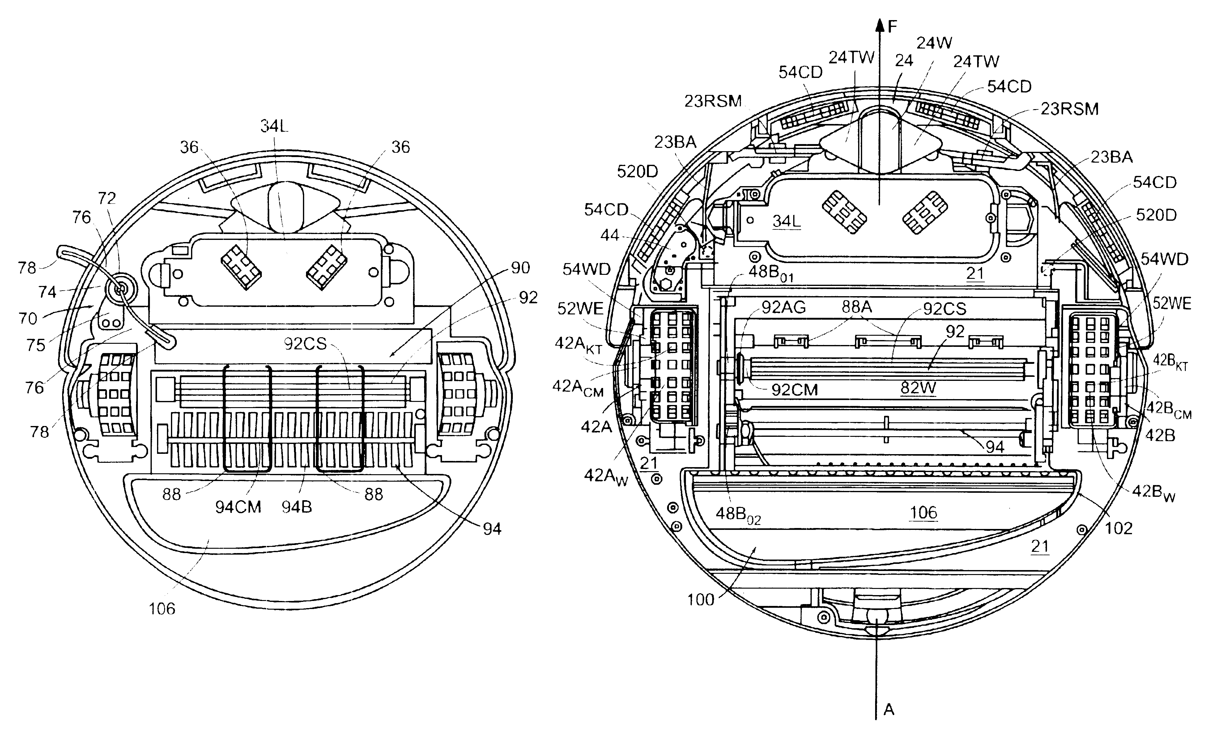
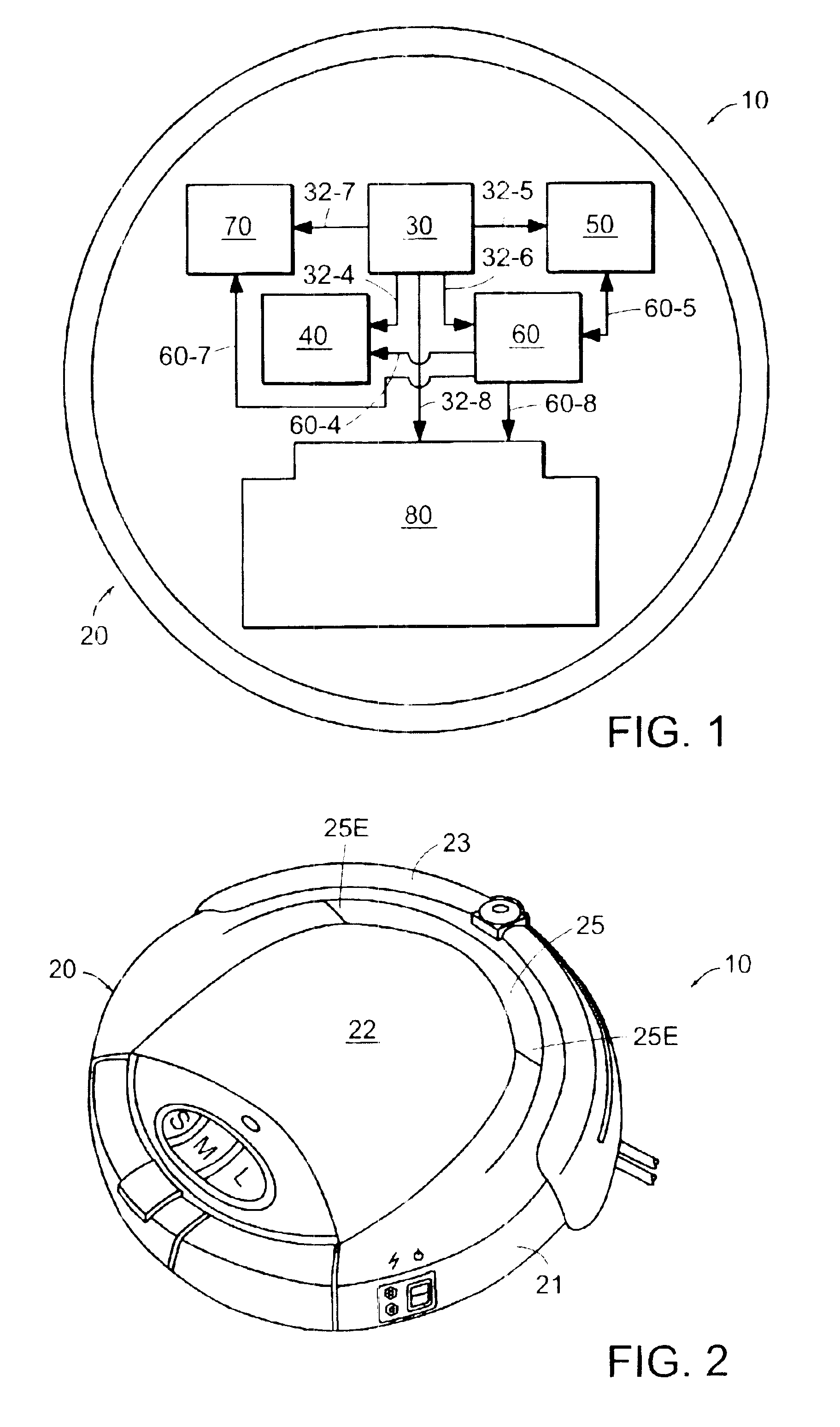
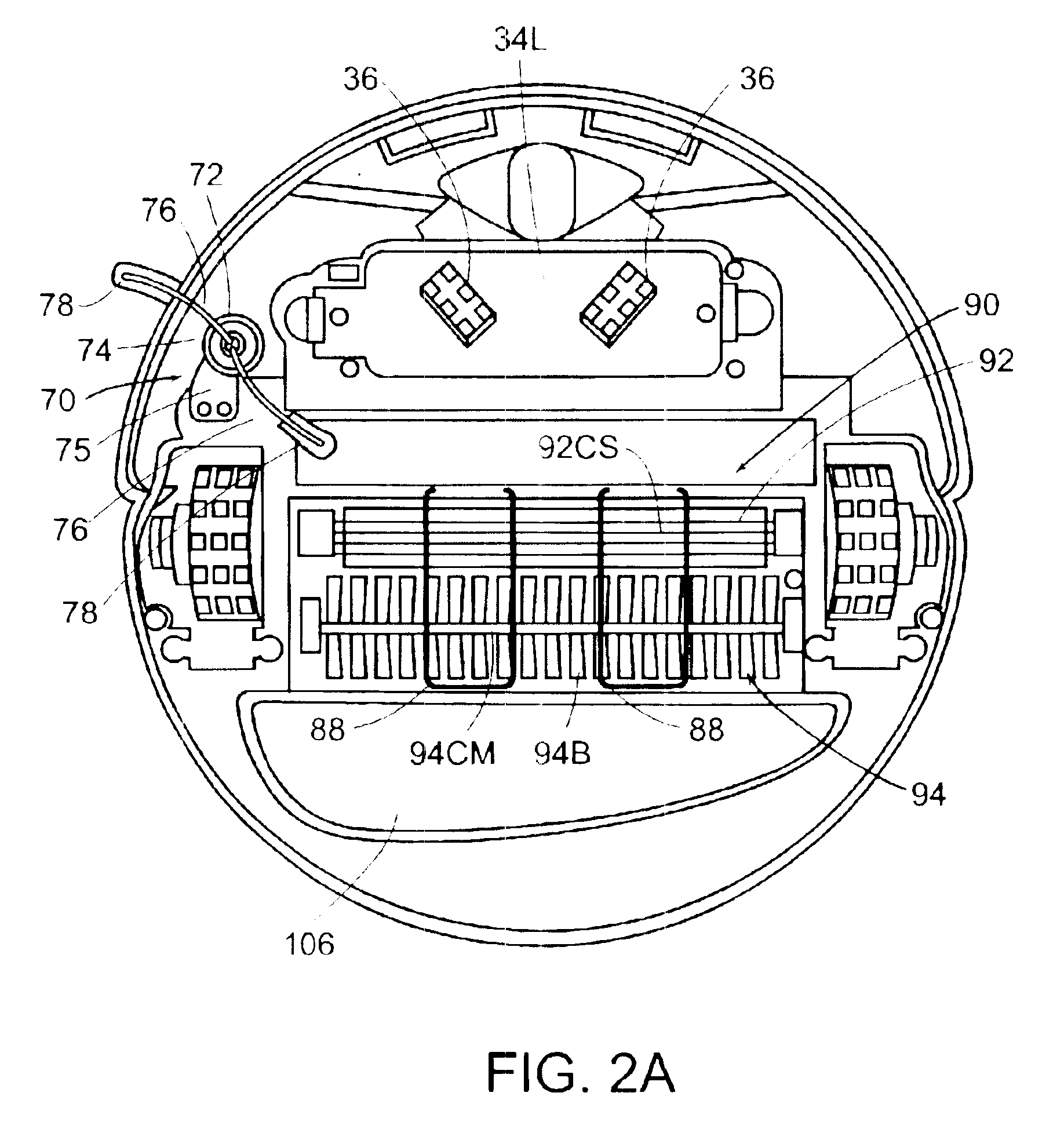
[0026]Referring now to the drawings where like reference numerals identify corresponding or similar elements throughout the several views, FIG. 1 is a schematic representation of an autonomous floor-cleaning robot 10 according to the present invention. The robot 10 comprises a housing infrastructure 20, a power subsystem 30, a motive subsystem 40, a sensor subsystem 50, a control module 60, a side brush assembly 70, and a self-adjusting cleaning head subsystem 80. The power subsystem 30, the motive subsystem 40, the sensor subsystem 50, the control module 60, the side brush assembly 70, and the self-adjusting cleaning head subsystem 80 are integrated in combination with the housing infrastructure 20 of the robot 10 as described in further detail in the following paragraphs.

[0027]In the following description of the autonomous floor-cleaning robot 10, use of the terminology “forward / fore” refers to the primary direction of motion of the autonomous floor-cleaning robot 10, and the term...


PUM


Abstract

An autonomous floor-cleaning robot comprises a self-adjusting cleaning head subsystem that includes a dual-stage brush assembly having counter-rotating, asymmetric brushes and an adjacent, but independent, vacuum assembly such that the cleaning capability and efficiency of the self-adjustable cleaning head subsystem is optimized while concomitantly minimizing the power requirements thereof. The autonomous floor-cleaning robot further includes a side brush assembly for directing particulates outside the envelope of the robot into the self-adjusting cleaning head subsystem.

Description


Claims


Application Information

Patent Timeline
Owner IROBOT CORP
Why Eureka
Try Eureka