Cooking oven with a cooled door that permits pyrolysis

a technology of pyrolysis and oven door, which is applied in the field of cooking oven, can solve the problems of obtaining the cooling of the outer pane at the expense of the effective cleaning of the inner pane, and achieve the effects of avoiding turbulence, enhancing the cooling of the outer pane, and simplifying assembly

Inactive Publication Date: 2005-06-14
ELECTROLUX HOME PROD CORP NV
View PDF45 Cites 51 Cited by
  • Summary
  • Abstract
  • Description
  • Claims
  • Application Information

AI Technical Summary

Benefits of technology

[0004]In accordance with one example feature, the present invention improves pyrolytic cleaning of the inner pane while ensuring effective cooling of the outer pane. Dividing the cooling into an active ventilation of the outer cavity and a partial or complete isolation of the inner cavities ensures that, while providing good cooling of the outer pane, the inner pane that is exposed to high temperatures can contribute effectively to the pyrolysis. The stationary intermediate air engenders high temperatures as well as a homogeneous temperature distribution and correspondingly effective combustion of particles on the inner pane.
[0006]In accordance with another example feature, the present invention provides that the outer legs of the U-profile of one or both longitudinal supports are provided with air-intake openings preferably positioned in one plane with the outer cavity and / or connecting to a channel that extends in alignment with the outer cavity, counteracting (near the cemented areas) any turbulence and lowering the temperature within the longitudinal support posts, on the side panels and on the outer oven surfaces of the unit. The air current laterally entering the longitudinal supports (door posts) can be controlled and indeed naturally optimized as a function of the lateral distance between the edge of the outer pane and a side ledge or a front frame, assuring an even temperature distribution across the entire surface of the outer pane.
[0008]In accordance with yet another example feature, the present invention provides that the U-shaped cross member connecting the legs of the U-profile transverse support is provided with air-exit vents preferably facing away from the outside area and pointing in the direction of the oven above the oven chamber. Here as well, to avoid turbulence and to enhance the cooling of the outer pane in the area of the door handle above the intermediate and inner panes, the transverse support is provided with a channel that is aligned with the outer cavity, connecting the latter with the air-exit vents.
[0009]In accordance with yet another example feature, the present invention provides that the transverse support is preferably mounted atop the longitudinal supports, connecting to these in a preferably detachable and, more specifically, in a slip-on fashion. In conjunction with the longitudinal supports after being detachably connected with them, it can be attached jointly with them to the outer pane, typically by cementing. This simplifies assembly and requires less cementing. The otherwise shorter leg of the U-profile is preferably extended from its two longitudinal ends to the inside of the outer pane where it, too, can be attached by cementing. For the purpose of reducing the temperature at the connecting or contact points the cemented areas may be interrupted by air gaps or applied for instance in a spot configuration.

Problems solved by technology

The cooling of the outer pane, however, is obtained at the expense of an effective cleaning of the inner pane by pyrolysis.

Method used


Image

  • Cooking oven with a cooled door that permits pyrolysis
  • Cooking oven with a cooled door that permits pyrolysis
  • Cooking oven with a cooled door that permits pyrolysis

Examples


Embodiment Construction

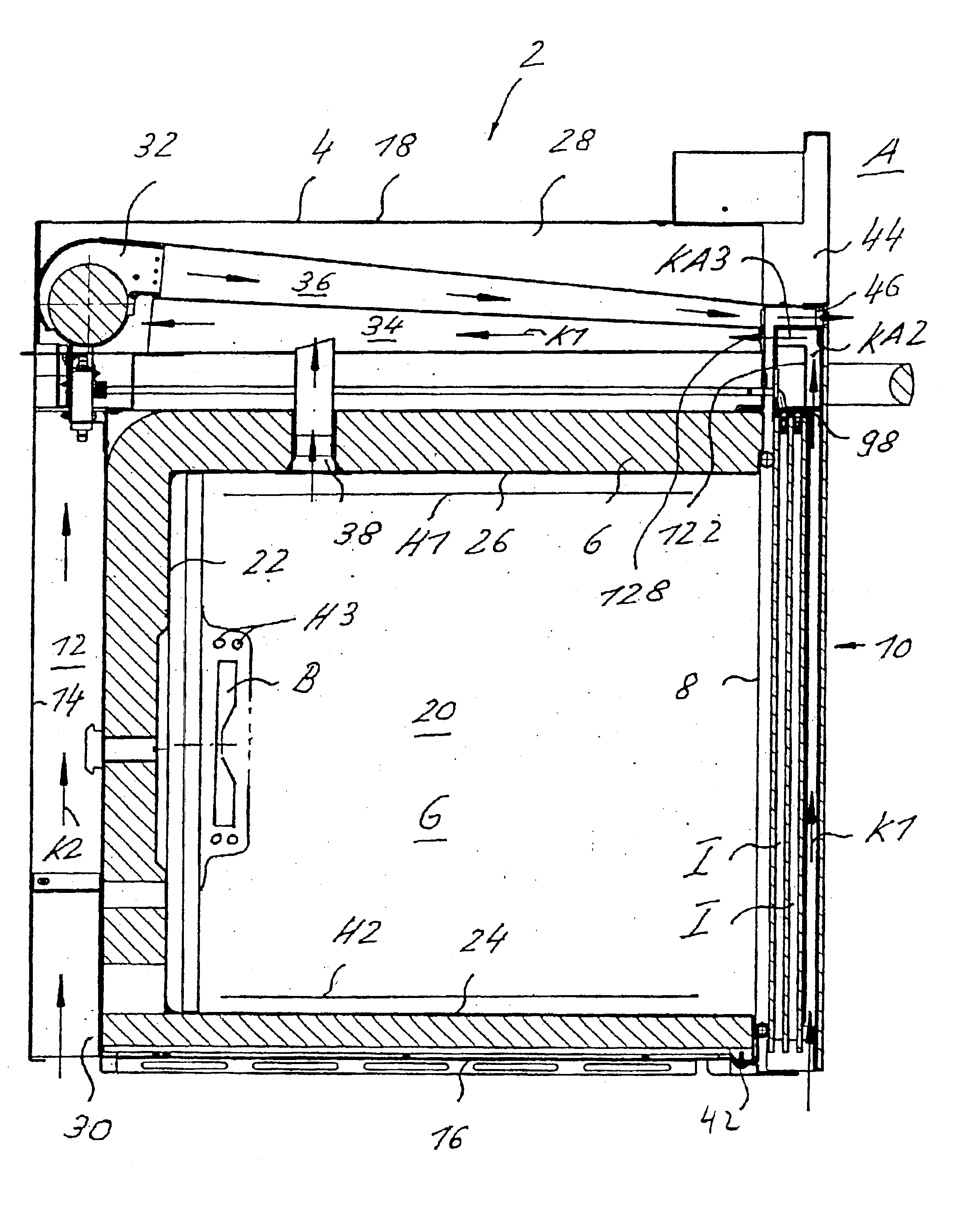
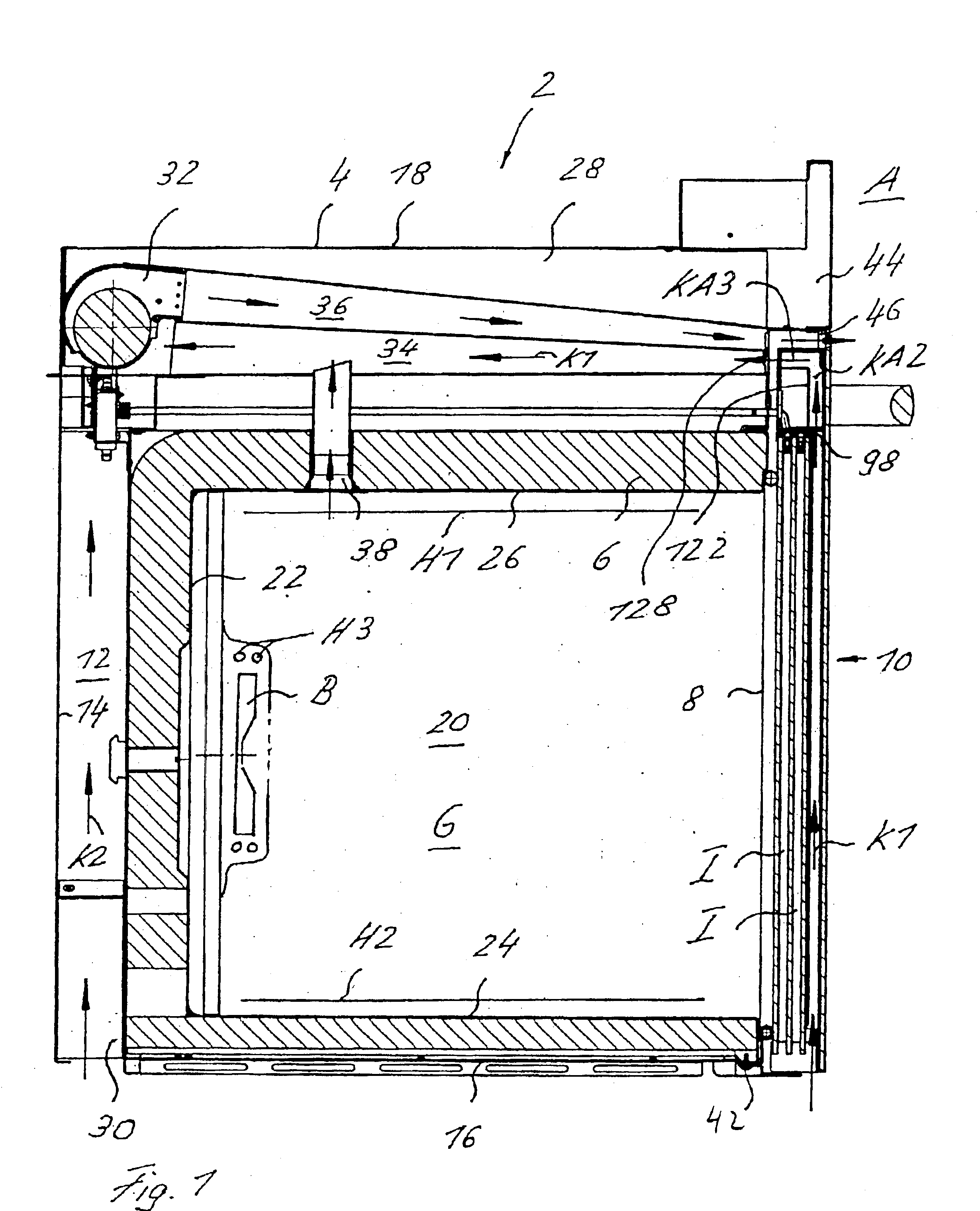
[0025]An example of an oven 2 that incorporates the present invention is shown in FIG. 1. The oven 2 includes a housing 4 that contains a heatable oven chamber 6 and a loading port 8 that can be closed by means of a door 10.

[0026]The housing 4 is a generally a cubic structure with an open front, and the oven chamber 6 has a generally cubic shape. The housing 4 has two mutually opposite side panels 12 (only one shown), a rear panel 14, a bottom panel 16 and a top panel 18. The oven chamber 6 has two mutually opposite side walls 20 (only one shown), a back wall 22, a bottom plate 24 and a top plate 26. Extending between the top panel 18 of the housing 4 and the top plate 26 of the oven chamber 6 is a horizontally extending clearance space 28. A vertical channel 30 is located between the rear panel 14 of the housing 4 and the back wall 22 of the oven chamber 6. The vertical channel 30 opens toward the bottom. A blower 32 is located in the area of the junction of the clearance space 28 ...


PUM


Abstract

A cooking oven includes a heatable oven chamber (6) that can be loaded with product from the outside area (A) through a loading port (8). An oven door (10) serves to close off the loading port (8) of the oven chamber (6) from the outside area (A). An inner pane (50) faces the oven chamber (6), an outer pane (48) faces the outside area (A), and one or several intermediate panes (52) are positioned between the inner pane (50) and the outer pane (48). An outer cavity (54) is between the outer pane (48) and the neighboring intermediate pane (52) and an inner cavity space (56) is between the inner pane (50) and the neighboring intermediate pane (52). A cooling system moves cooling air (K1) through the outer cavity (54) while thermally insulating air (I) can be held stationary in the inner cavity (56).

Description

FIELD OF THE INVENTION[0001]The present invention relates to a cooking oven equipped with a heatable oven chamber loadable, with product to be cooked, from the outside through a loading port, and an oven door that serves to close off the loading port of the oven chamber from the outside. The present invention specifically relates to a cooking oven that incorporates an inner pane facing the oven chamber, an outer pane facing the outside area, and one or more intermediate panes positioned between the inner and the outer panes.BACKGROUND OF THE INVENTION[0002]In an earlier oven design per DE 100 47 016 A1, cooling air is drawn in between an outer pane and a neighboring intermediate pane, from there into the space or cavity between two intermediate panes and finally into the space between an intermediate pane and the inner pane, ultimately to be exhausted again. The cooling of the outer pane, however, is obtained at the expense of an effective cleaning of the inner pane by pyrolysis.SUM...

Claims


Application Information

Patent Timeline
Patent Type & Authority Patents(United States)
IPC IPC(8): F24C15/02F24C15/04F24C15/00
CPCF24C15/006F24C15/2007F24C15/04
Inventor WALTHER, CHRISTOPHPORNER, HARALDPELIC, VLADMIRMCKECHNIE, ROBERTMURGUET, PATRICEHILDNER, DIETMAR
Owner ELECTROLUX HOME PROD CORP NV
Why Eureka
Try Eureka