Thread-forming screw fastener

a screw and thread technology, applied in the direction of thread fasteners, screws, fastening means, etc., can solve the problems of making the release of the screw fastener more difficult, and achieve the effect of favorable influence of tapping torque during the insertion and small tapping torqu

Active Publication Date: 2006-09-05
SPAX INT
View PDF17 Cites 33 Cited by
  • Summary
  • Abstract
  • Description
  • Claims
  • Application Information

AI Technical Summary

Benefits of technology

[0006]According to the invention, this is achieved in that the first apex angle between the flanks in their uninterrupted regions of the wave crests is approximately within the range of 30° to 35°, and in that the second apex angle in the region of the niches and wave troughs is 30° up to at most 58°. According to the invention, the apex angles are therefore smaller compared with the prior art, thereby resulting in a slimmer thread profile, so that the tapping torque during the insertion is favorably influenced by virtue of the fact that the thread more easily forms a mating thread in the respective material by material displacement, i.e. essentially without chip formation. In this case, a difference in angle between the first and second apex angles should be as small as possible or even zero, i.e. the second apex angle in the region of the wave troughs and the niches should be as small as possible in order to keep the tapping torque small due to a slim profile form. A continuous, virtually edge-free transition between the thread flanks and niches is also advantageous in this case.
[0011]In particular in combination with one or more of the inventive features explained, it is advantageous if the thread of single-start design in practice has a pitch which is about 0.5 times the outer thread diameter (screw fastener nominal diameter). In this way, increased feed for quicker insertion is achieved. Nonetheless, according to the invention, a high release torque for lasting prestress of the screwed connection is ensured.

Problems solved by technology

During the insertion, the resistance due to the flatter design of the rear parabolic parts in the insertion direction is lower, whereas the release of the screw fastener is made more difficult on account of the steeper arrangement of the parabolic areas lying at the front in the insertion direction.

Method used


Image

  • Thread-forming screw fastener
  • Thread-forming screw fastener
  • Thread-forming screw fastener

Examples


Embodiment Construction

[0024]In the various figures of the drawing, the same parts are always provided with the same reference numerals and are therefore as a rule only described once in each case.

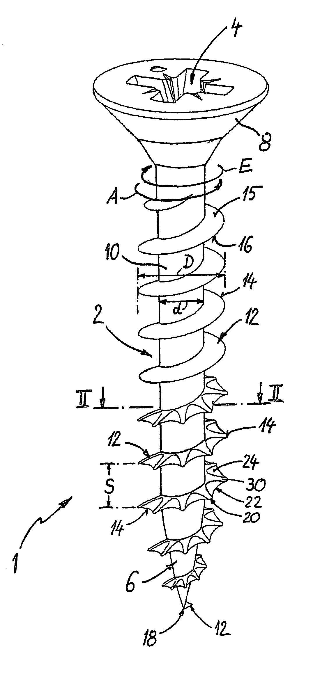
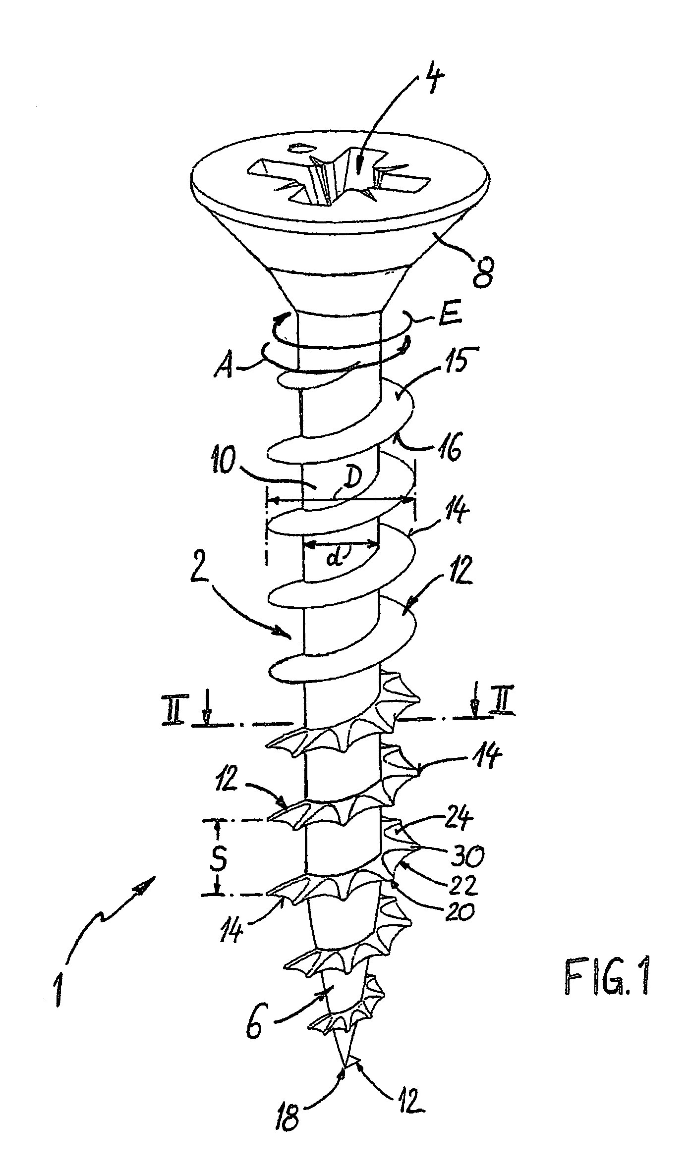
[0025]As can be seen first of all from FIG. 1, a screw fastener 1 according to the invention consists of a threaded shank 2 having a force application means 4 at one end for torque transmission and an opposite screw fastener point 6. In the example shown, the force application means 4 is designed in the form of a recess as an internal force application means, here purely by way of example as a cross recess, in a screw fastener head 8 designed as a countersunk head. The threaded shank 2 consists of a preferably cylindrical shank core 10 having a core diameter d (see also FIG. 2) and a self-tapping, in particular single-start, thread 12 having an outer thread diameter (screw fastener nominal diameter) D (FIGS. 1 and 2), this thread 12 being designed as a prominence (only one prominence) running helically at least ...


PUM

PropertyMeasurementUnit
apex angleaaaaaaaaaa

Abstract

The invention relates to a screw fastener comprising a threaded shank having a force application means for torque transmission and a screw fastener point. The threaded shank consists of a shank core and a self-tapping thread, and the thread is designed as a prominence which runs helically over the shank core, is defined by two flanks meeting in an outer thread edge and has a radial height (H). The outer thread edge, at least in a section of the thread, runs in a wavelike manner in the radial direction with an amplitude between wave crests having the height (H) and wave troughs having a height (h) reduced by the amplitude. The thread, at least in the region of one of its flanks, has niches in the region of the wave troughs of the thread edge, which niches interrupt the surface of the flank and their outer boundary is the thread edge, the thread in each case having a certain first apex angle (α), formed between the flanks, in those regions of the wave crests of the thread edge which are not interrupted by niches and a second apex angle (α′) in the deepest regions of the wave troughs of the thread edge. The first apex angle (α) between the flanks is approximately within the range of 30° to 35°, the second apex angle (α′) being 30° up to at most 58°.

Description

CROSS REFERENCE TO RELATED APPLICATION[0001]This application claims priority to German Utility Model application number 20 2004 002 877.8 filed Feb. 25, 2004.BACKGROUND OF THE INVENTION[0002]The present invention relates to a screw fastener comprising a threaded shank having a force application means for torque transmission and a screw fastener point. The threaded shank consisting of a shank core and a self-tapping thread, and the thread being designed as a prominence which runs helically over the shank core, is defined by two flanks meeting in an outer thread edge and has a height measured radially between the core and the thread edge. The outer thread edge, at least in a section of the thread, running in a wavelike manner in the radial direction with a certain amplitude between wave crests having the thread height and wave troughs having a height reduced by the amplitude, and the thread, at least in the region of one of its flanks, having niches in the region of the wave troughs o...

Claims


Application Information

Patent Timeline
Patent Type & Authority Patents(United States)
IPC IPC(8): F16B25/10F16B35/04F16B39/30F16B25/00F16B33/02
CPCF16B25/0015F16B25/0057F16B25/0052F16B25/0047
Inventor DICKE, ROBERT
Owner SPAX INT
Why Eureka
Try Eureka