AI technical title is built by PatSnap AI team. It summarizes the technical point description of the patent document.
a technology for identification systems and apparatus, applied in the field of system and method for identifying items, can solve the problems of rfidt so positioned failing and being of no further use, and rfidt so positioned being subject to damage above ground
Active Publication Date: 2007-01-09
VARCO I P INC
View PDF48 Cites 185 Cited by
Summary
Abstract
Description
Claims
Application Information
AI Technical Summary
This helps you quickly interpret patents by identifying the three key elements:
Problems solved by technology
Method used
Benefits of technology
Benefits of technology
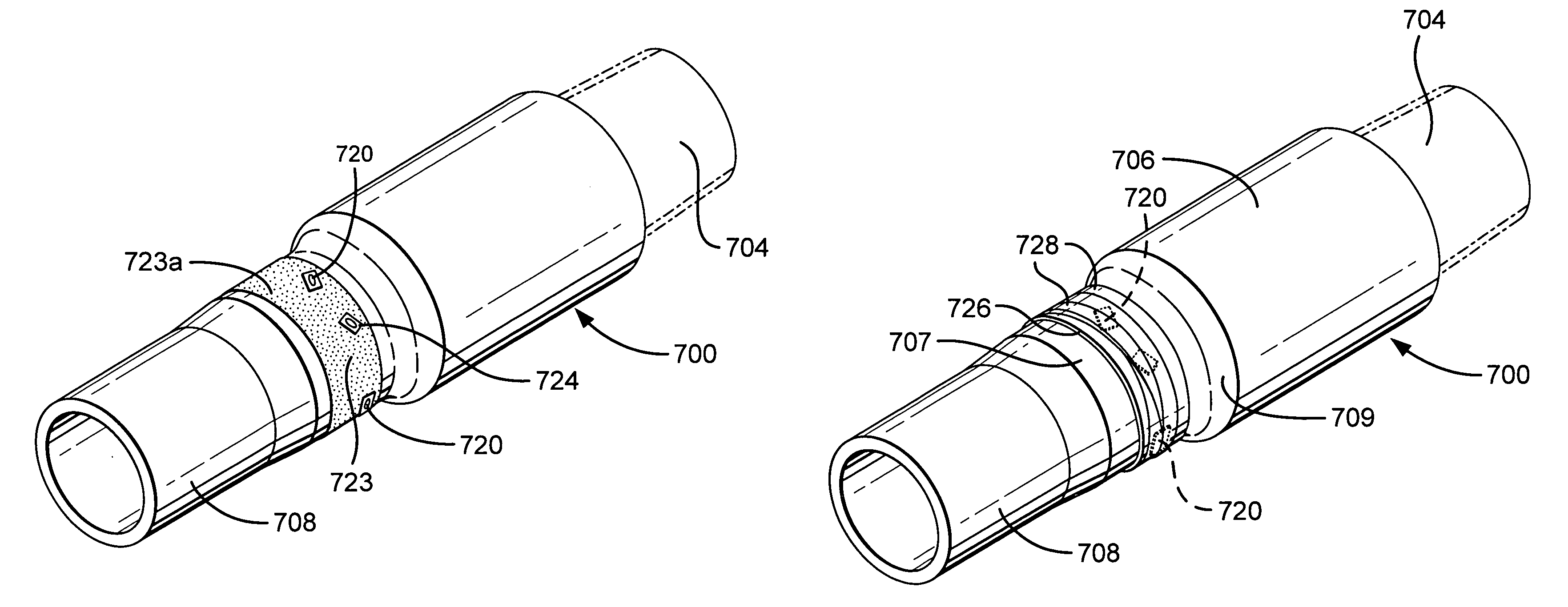
[0008]The present invention, in certain aspects, provides an item, apparatus, or tubular, e.g. a piece of drill pipe, with one or more radio frequency identification tags wrapped in heat and impact resistant materials; in one aspect, located in an area 2–3″ in length beginning ½ from the 18 degree taper of the pin and drill pipe tool joint so that the RFIDT (or RFIDT's) is protected from shocks (pressure, impacts, thermal) that may be encountered on a rig, in a wellbore, or during wellbore (e.g. drilling or casing) operations. In one particular aspect, the present invention discloses systems and methods in which a piece of drill pie with threaded pin and box ends has one or more radio frequency identification tags each with an integrated circuit and with an antenna encircling the pin end upset area located exteriorly on the pipe, e.g. in an area ½″–2½″ from a pin end 18 degree taper. The RFIDT (or RFIDT's) is protected by wrapping the entire RFIDT and antenna in a heat resistant material wrapped around the circumference of the tube body and held in place by heat resistant glue or adhesive, e.g. epoxy material which encases the RFIDT. This material is covered with a layer of impact resistant material and wrapped with multiple layers of wrapping material such as epoxy bonded wrap material. Preferably this wrapping does not exceed the tool joint OD. The RFIDT can be (as can be any disclosed herein), in certain aspects, any known commercially-available read-only or read-write radio frequency identification tag and any suitable know reader system, manual, fixed, and / or automatic may be used to read the RFIDT. Such installation of RFIDT's can be carried out in the field, in a factory, on a rig, with no machining necessary. Optionally, a metal tag designating a unique serial number of each item, apparatus, or length of drill pipe located under the wrap with the RFIDT(s) insures “Traceability” is never lost due to failure of the RFIDT(s). Replacement of failed RFIDT's can be carried out without leaving a location, eliminating expensive transportation or trucking costs. Optionally the wrap is applied in a distinctive and / or a bright color for easy identification. Determining whether an item, apparatus, or a tubular or a length of drill pipe or a drill pipe string is RFID-tagged or not is visibly noticeable, e.g. from a distance once the RFIDT's are in place.
[0010]With an RFIDT located in a pipe's pin end as described herein, upon makeup of a joint including two such pieces of pipe, an RFIDT in one pipe's pin end is completely surrounded by pipe material—including that of a corresponding pipe's box end—and the RFIDT is sealingly protected from access by materials flowing through the pipe and from materials exterior to the pipe. The mass of pipe material surrounding the enclosed RFIDT also protects it from the temperature extremes of materials within and outside of the pipe.
Problems solved by technology
Often an RFIDT so positioned fails and is of no further use.
Also, in many instances, an RFIDT so positioned is subjected to damage above ground due to the rigors of handling and manipulation.
Method used
Image
Click on the blue label to locate the original text in one second.
Reading with bidirectional positioning of images and text.
Examples
Embodiment Construction
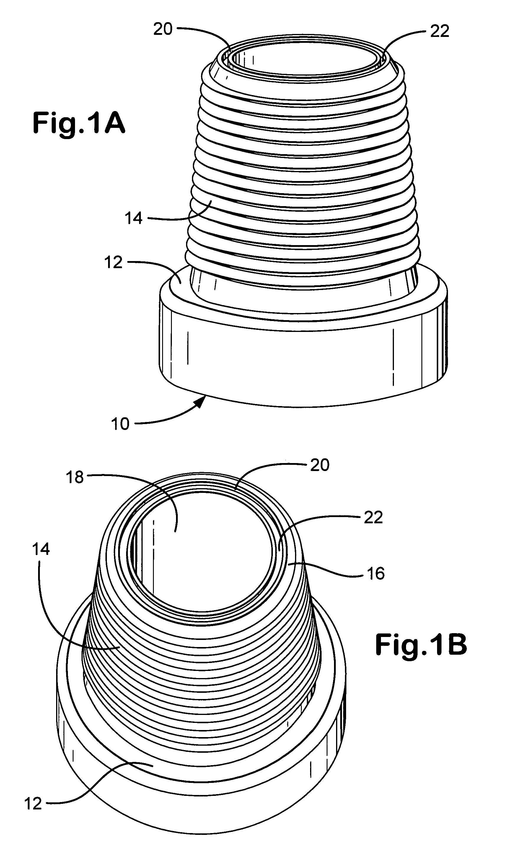
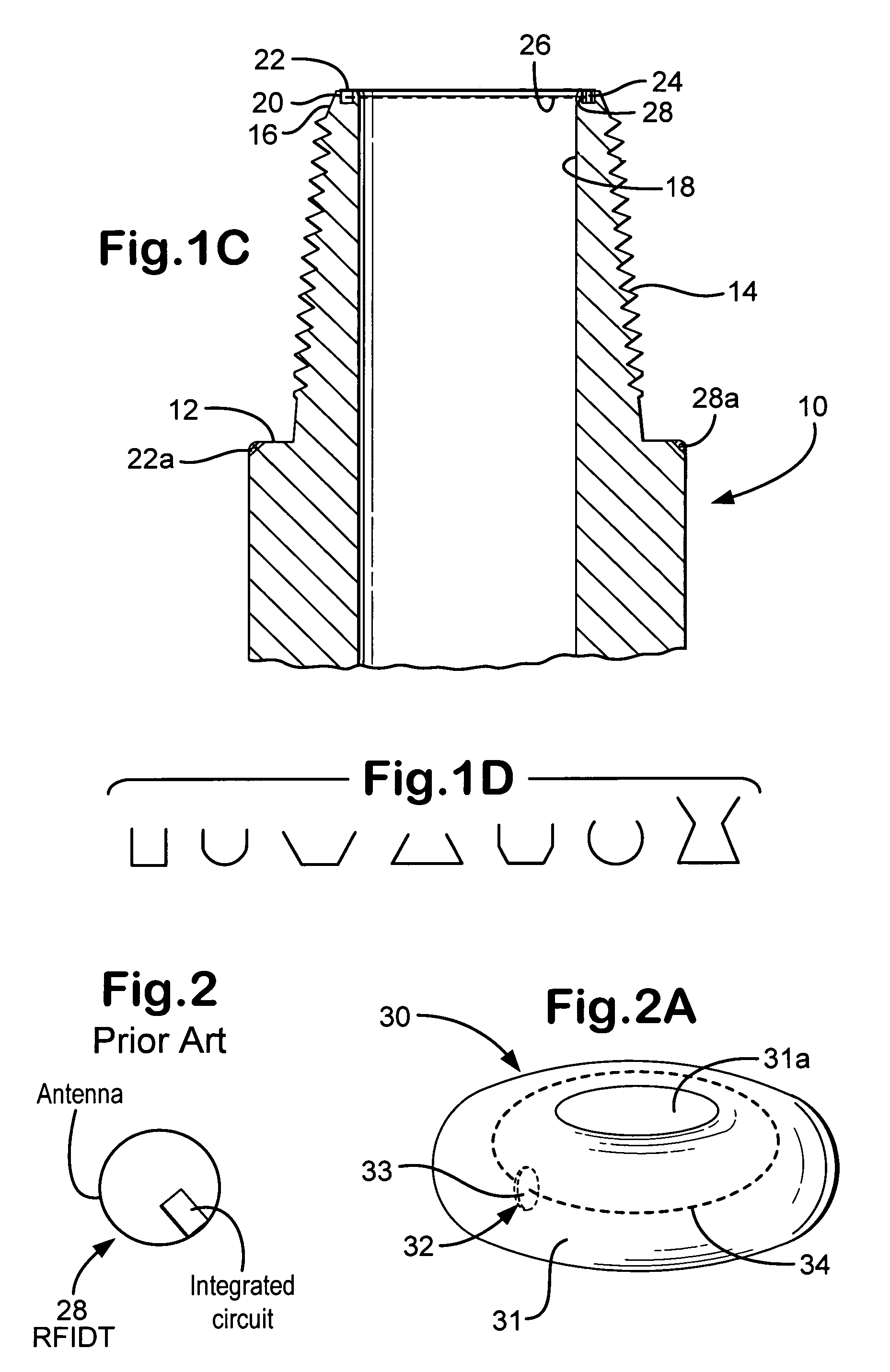
[0062]FIGS. 1A–1C show a pin end 10 of a drill pipe according to the present invention which has a sealing shoulder 12 and a threaded end portion 14. A typical flow channel 18 extends through the drill pipe from one end to the other. A recess 20 in the top 16 (as viewed in FIG. 1C) of the pin end 10 extends around the entire circumference of the top 16. This recess 20 is shown with a generally rectangular shape, but it is within the scope of this invention to provide a recess with any desired cross-sectional shape, including, but not limited to, the shapes shown in FIG. 1D. In one aspect an entire drill pipe piece with a pin end 10 is like the tubular shown in FIG. 3A or the drill pipe of FIG. 12B. The recess 20 (as is true for any recess of any embodiment disclosed herein) may be at any depth (as viewed in FIG. 1C) from the end of the pin end and, as shown in FIGS. 1A–1C may, according to the present invention, be located so that no thread is adjacent the recess.
[0063]It is within ...
PUM
Abstract
A member having a body, the body having two spaced-apart ends, wave energizable identification apparatus which, in one aspect, is radio frequency identification apparatus with integrated circuit apparatus and antenna apparatus on the exterior of the body, and encasement structure encasing the identification apparatus, the encasement structure, in certain aspects, including one or a plurality of layers of heat resistant material and, in certain aspects, at least one layer of heat resistant material, and methods for producing such a member.
Description
RELATED APPLICATION[0001]This is a continuation-in-part of U.S. application Ser. No. 10 / 825,590 filed Apr. 15, 2004, incorporated fully herein and from which the present invention claims priority under the Patent Laws.BACKGROUND OF THE INVENTION[0002]1. Field of the Invention[0003]This invention is directed to systems and methods for identifying items; and, in certain aspects to identifying items in the oil and gas industry; and in one particular aspect to identifying tubulars, including, but not limited to, pieces of drill pipe, using radio frequency identification devices and / or sensible indicia.[0004]2. Description of Related Art[0005]The prior art discloses a variety of systems and methods for using surface acoustic wave tags or radio frequency identification tags in identifying items, including items used in the oil and gas industry such as drill pipe. (See e.g. U.S. Pat. Nos. 4,698,631; 5,142,128; 5,202,680; 5,360,967; 6,333,699; 6,333,700; 6,347,292; 6,480,811; and U.S. paten...
Claims
Application Information
Patent Timeline
Application Date:The date an application was filed.
Publication Date:The date a patent or application was officially published.
First Publication Date:The earliest publication date of a patent with the same application number.
Issue Date:Publication date of the patent grant document.
PCT Entry Date:The Entry date of PCT National Phase.
Estimated Expiry Date:The statutory expiry date of a patent right according to the Patent Law, and it is the longest term of protection that the patent right can achieve without the termination of the patent right due to other reasons(Term extension factor has been taken into account ).
Invalid Date:Actual expiry date is based on effective date or publication date of legal transaction data of invalid patent.

