Apparatus and method for deinterlace video signal

a video signal and apparatus technology, applied in the field of apparatus and method for deinterlacing video signals, can solve the problems of reducing the vertical resolution of half, degrading the picture quality, and conspicuous degrading of the picture quality, so as to improve the picture quality

Inactive Publication Date: 2007-01-30
MACRO IMAGE TECH
View PDF6 Cites 49 Cited by
  • Summary
  • Abstract
  • Description
  • Claims
  • Application Information

AI Technical Summary

Benefits of technology

[0014]An object of the present invention is to provide a motion adaptive deinterlace method and several techniques for improving a picture quality much more compared with a conventional method.

Problems solved by technology

The reason is that degradation of the picture quality is conspicuous when the still images consisting of dots and lines are displayed based on the interlaced scanning method.
On the other hand, a flat panel display device employing PDP, LCD and DLP does not perform the high voltage deflection.
Accordingly, the flat panel display device uses the progressive scanning method rather than the interlaced scanning method, since the interlaced scanning method has drawbacks of line flicker, large area flicker, detection of a scanning line, and the like.
Although the line repetition method can be implemented with the simplest hardware, it has a disadvantage that degrades the picture quality since a boundary of an inclined line seems a stepped shape after the interpolation.
However, the intra-field interpolation method makes frames by using only information on one field with respect to the still image, thus lowering a vertical resolution by half.
However, since this is similar to the overlap of two images, whose timings are somewhat different from each other, the inter-field interpolation method has a disadvantage in that the flicker may occur in a screen when the moving image is entirely displayed.
Particularly, a partial flicker occurs seriously in an image having much noise.
In case most of the images are the moving images and some of them are the still images, noise occurs at a boundary area between the moving image and the still image due to noise occurring in the extraction of the motion value.
It is desirable not to use the above-described hardware because the conversion of the interlaced scanning image into the progressive scanning image results in the degradation of the picture quality.

Method used


Image

  • Apparatus and method for deinterlace video signal
  • Apparatus and method for deinterlace video signal
  • Apparatus and method for deinterlace video signal

Examples


Embodiment Construction

[0059]Hereinafter, an apparatus and method for deinterlacing video signals in accordance with the present invention will be described in detail with reference to the accompanying drawings.

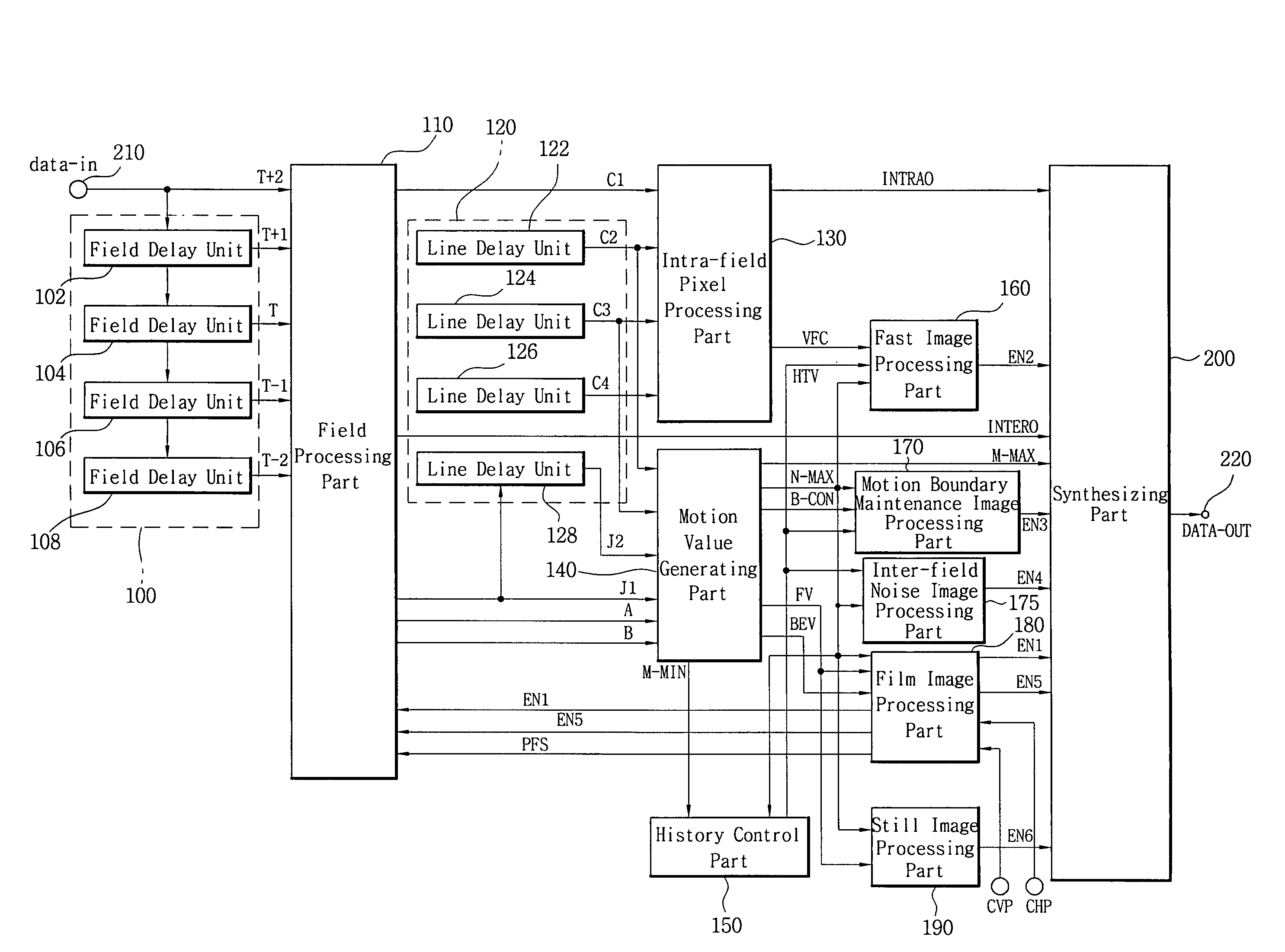
[0060]FIG. 1 is a block diagram showing an overall construction of an apparatus for deinterlacing video signals in accordance with the present invention.

[0061]According to the apparatus of the present invention, a current-field image data T+2 is inputted through an input terminal 210 and a sequential field delay part 100 stores the current-field image data T+2 into first to fourth field delay units 102, 104, 106 and 108 by field unit and sequentially outputs the stored field image data.

[0062]A field processing part 110 processes the current-field image data T+2, a one-field delayed image data T+1, a two-field delayed image data T, a three-field delayed image data T−1 and a four-field delayed image data T−2 in response to an external caption display mode signal EN5, a film mode signal EN1 and an int...


PUM


Abstract

There is provided an image signal deinterlacing apparatus for converting an interlaced scanning image into a progressive scanning image. The deinterlacing apparatus includes: an intra-field pixel processing unit for detecting a face area and a to-be-interpolated data within a field by using pixels of a field disposed before two field from a current field; a motion value generating unit for detecting first to third motion values and first and second motion degree values; a history control unit for detecting a history value; a fast image processing unit for detecting a fast motion image; a film image processing unit for detecting a film image and a caption area and determining a to-be-interpolated field data; a still image processing unit for accumulating the first motion value and the second motion degree value to detect a still image; an inter-field noise image processing unit for detecting an adjacent inter-field noise image; a motion boundary maintenance image processing unit for detecting a motion boundary maintenance image; and a synthesizing unit for selectively interpolating the intra-field to-be-interpolated data, the before-one-field inter-field data and the before-three-field inter-field data according to the detection result.

Description

BACKGROUND OF THE INVENTION[0001]1. Field of the Invention[0002]The present invention relates to a method for deinterlacing video signals, and more particularly, to an apparatus and method for deinterlacing video signals, in which clearer picture quality can be secured by solving a variety of phenomena, such as step pattern image, horizontal moire pattern afterimage, noise and the like, which occur when an interlaced scanning image consisting of fields is converted into a progressive scanning image consisting of the same number of frames according to image modes. In addition, a still image, a film mode image and a caption image can be displayed in a resolution close to a photograph and also restored closely to an original image, thereby improving a picture quality.[0003]2. Description of the Related Art[0004]Generally, a display of interlaced scanning images is implemented by alternating odd fields (i.e., an odd line group of screen) and even fields (i.e., an even line group of scre...

Claims


Application Information

Patent Timeline
Patent Type & Authority Patents(United States)
IPC IPC(8): H04N7/01G09G5/00G09G5/36G09G5/391
CPCH04N7/012H04N7/0112H04N7/01
Inventor YOO, DAE-WOONYANG, DU-SIK
Owner MACRO IMAGE TECH
Why Eureka
Try Eureka