Hot runner co-injection nozzle

Active Publication Date: 2007-02-13
MOLD MASTERS 2007
View PDF93 Cites 18 Cited by
  • Summary
  • Abstract
  • Description
  • Claims
  • Application Information

AI Technical Summary

Benefits of technology

[0030]The present invention provides an advantage for multi-material molding in that a metered quantity of a melt is delivered accurately and consistently to a single or a plurality of

Problems solved by technology

Several devices have been developed to control the volume of melt that is injected into a multi-material mold cavity, however, these devices tend to be inaccurate, difficult to operate, complex and costly to manufacture.
A disadvantage of these manifold shooting pots is that they are remotely located from the nozzle and the mold cavity and this makes the whole apparatus more space consuming.
Also these shooting pots located in the manifold or adjacent the manifold include separate mechanisms located in the manifold that open and close the access of the metered molten material to the shooting

Method used


Image

  • Hot runner co-injection nozzle
  • Hot runner co-injection nozzle
  • Hot runner co-injection nozzle

Examples


Embodiment Construction

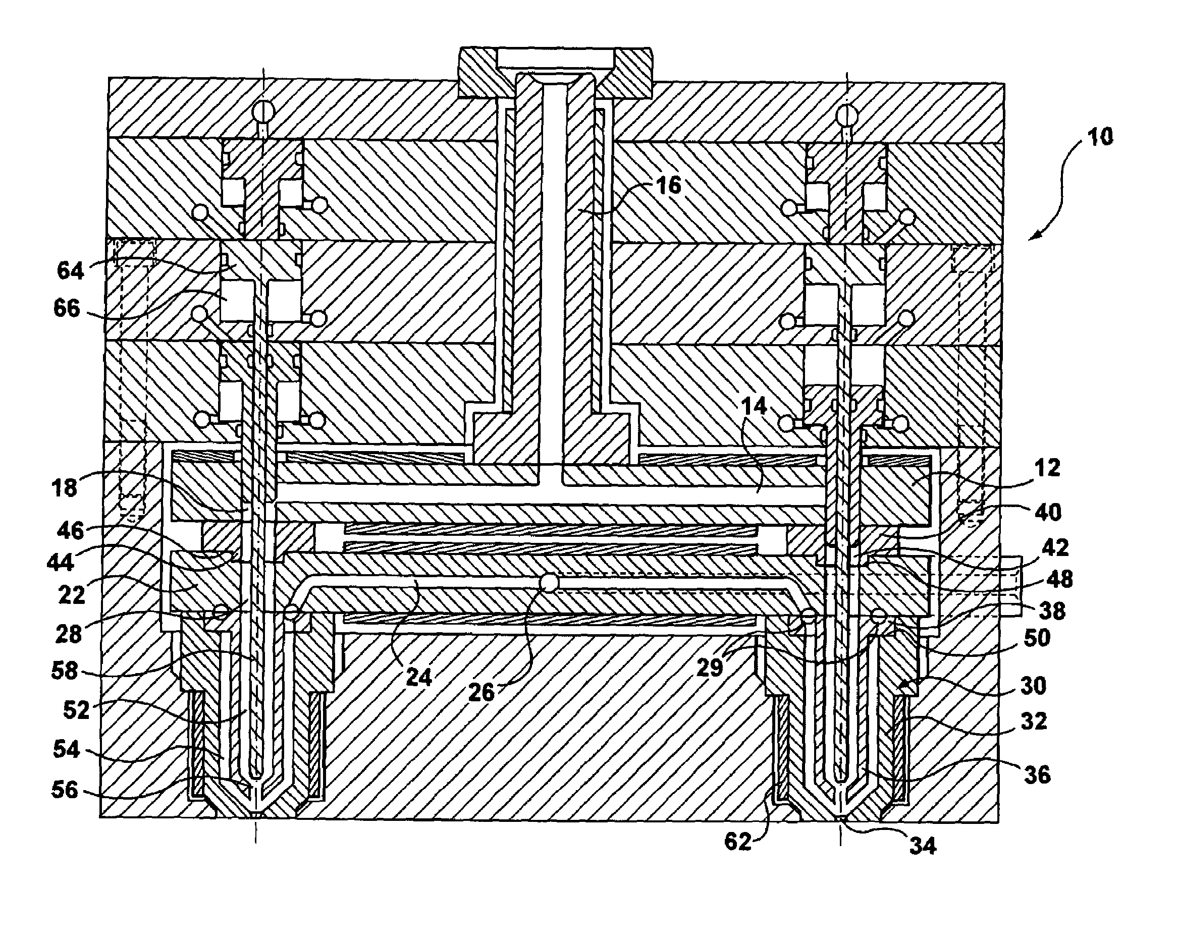
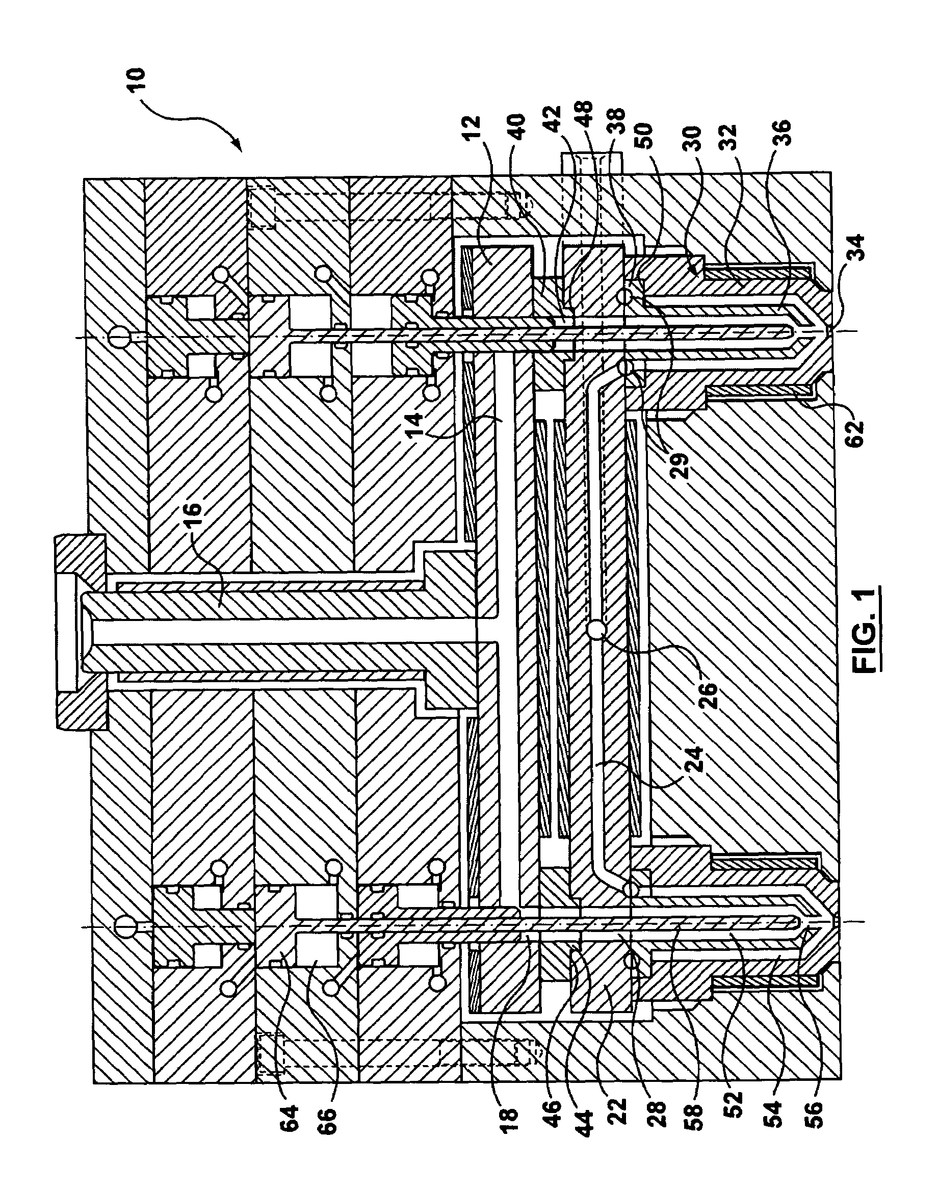
[0038]Referring to FIG. 1, portions of a co-injection molding apparatus are generally shown at 10. The co-injection molding apparatus 10 includes a first manifold 12 having a first manifold melt channel 14 for receiving a first melt stream of moldable material under pressure from a first manifold bushing 16. The first manifold bushing 16 is in communication with a first machine nozzle (not shown). Bores 18 extend through the first manifold 12 at distal ends of the first manifold melt channel 14. The bores 18 are in communication with the first melt channel 14 and extend generally perpendicular thereto.

[0039]The injection molding apparatus 10 further comprises a second manifold 22 having a second manifold melt channel 24 for receiving a second melt stream of moldable material under pressure through an inlet 26 from a second manifold bushing (not shown). Bores 28 extend through the second manifold 22 at distal ends of the second manifold 22 and extend generally perpendicular thereto. ...


PUM

PropertyMeasurementUnit
Compositionaaaaaaaaaa
Melting pointaaaaaaaaaa

Abstract

This invention teaches a hot runner injection molding apparatus for co-injecting at least two different materials into a mold cavity. A pin valve gated hot runner nozzle includes separate melt channels for each material and a melt chamber for accurately metering one of the materials. The melt chamber is in communication with an injection piston. The controlled movement of the valve pin and of the injection piston insures that the desired amount of a first and at least a second material is injected into the mold cavity. Depending of the composition and the processing window of the materials, the co-injection hot runner nozzle is in communication with either a single or multiple manifolds.

Description

CROSS-REFERENCE TO RELATED APPLICATIONS[0001]This application claims the benefit under 35 U.S.C. § 119(e) of provisional application No. 60 / 430,358, filed Dec. 3, 2002, which is incorporated by reference in its entirety herein.FIELD OF THE INVENTION[0002]The present invention relates generally to a co-injection molding apparatus, and in particular to a metering device for a hot runner nozzle, which injects a predetermined quantity of melt into a mold cavity. The present invention is applicable to molding applications in which two or more materials are injected simultaneously and / or sequentially into a single mold cavity.BACKGROUND OF THE INVENTION[0003]In a co-injection molding apparatus, two or more molten materials are injected into the same mold cavity, either simultaneously or in sequence using a single or a plurality of injection manifolds. A typical co-injection molding apparatus comprises first and second injection manifolds that receive pressurized melt streams from respecti...

Claims


Application Information

Patent Timeline
IPC IPC(8): B29C45/23B29C45/27B29C45/02B29C45/16B29C45/28
CPCB29C45/1603B29C45/02B29C2045/2848B29C45/28B29C45/2806B29C45/2725
Inventor BABIN, DENIS
Owner MOLD MASTERS 2007
Why Eureka
Try Eureka