Conveyor belt

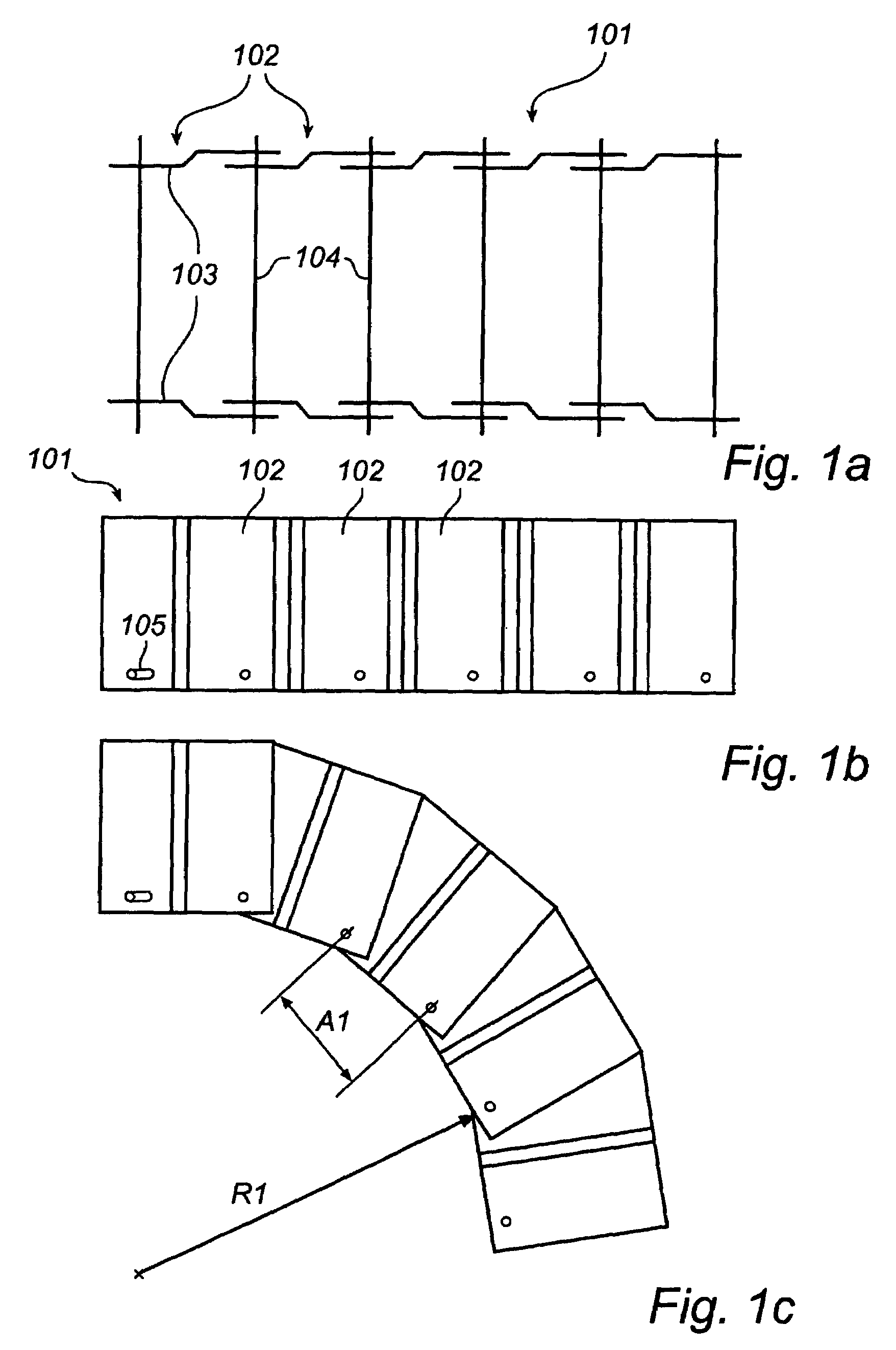
a conveyor belt and belt technology, applied in the field of conveyor belts, can solve the problems of limited load-bearing capacity and serious drawbacks of the prior-art conveyor belt b>101/b>, and achieve the effect of adversity and great torsional rigidity

Inactive Publication Date: 2007-02-20
JOHN BEAN TECH AB
View PDF6 Cites 16 Cited by
  • Summary
  • Abstract
  • Description
  • Claims
  • Application Information

AI Technical Summary

Benefits of technology

[0021]A further object is to provide such a conveyor belt which exhibits good turnability in the vertical direction.
[0031]According to yet another preferred embodiment, elongate holes are formed in the coupling element to receive said neighbouring rods of the adjoining link means. The elongate holes enable said movability of the link means in the longitudinal direction of the conveyor belt and also the turnability of the conveyor belt in the lateral direction.

Problems solved by technology

This prior-art type of conveyor belt 101, however, suffers from a serious drawback.
The link means 102 of the conveyor belt 101 exhibit relatively low rigidity, which means that its load-bearing capacity is limited.
In some cases, however, the design of the link means causes difficulties.

Method used


Image

  • Conveyor belt
  • Conveyor belt
  • Conveyor belt

Examples


Embodiment Construction

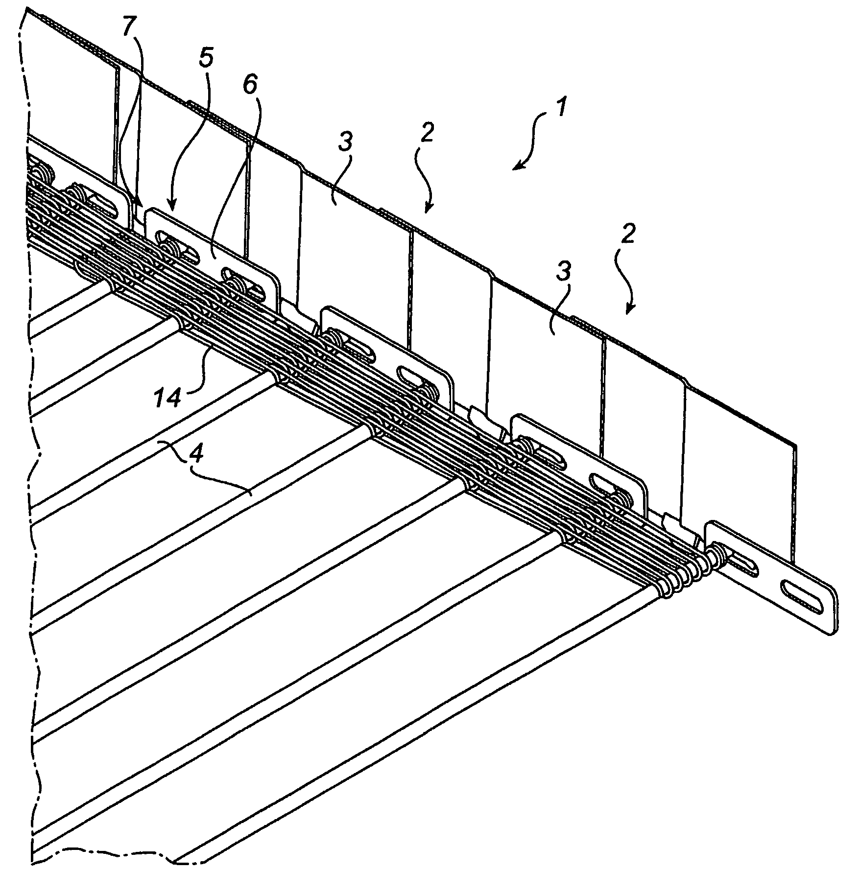
[0044]The present invention relates to an endless conveyor belt 1 for an air conditioning plant, in which the conveyor belt 1 extends helically along part of its length. The conveyor belt 1 thus is intended to be arranged in an endless loop, for instance, as shown in FIG. 3. The conveyor belt 1 can be intended for conveying of foodstuffs, which will be quick-frozen when conveyed through the air conditioning plant.

[0045]However, it will be appreciated that the inventive conveyor belt can also be used for other applications than air conditioning plants.

[0046]The present invention will now be described with reference to a schematic, basic embodiment and to preferred embodiments. Equivalent components have been given the same reference numerals.

[0047]FIGS. 4a–c, to which reference is now made, schematically illustrate an inventive conveyor belt 1.

[0048]The conveyor belt 1 comprises a plurality of link means 2, which each have two lateral elements 3 and two rods 4 extended between and fi...


PUM


Abstract

An endless conveyor belt for an air conditioning plant, in which the conveyor belt extends helically along part of its length, comprising transverse rods (4) and lateral elements (3). The conveyor belt is characterized in that the lateral elements (3) are connected in pairs to only two rods (4), which are fixedly connected to said lateral elements (3) and form, with these, a link means (2), and adjoining link means (2) are articulated to each other by a coupling element (5) arranged therebetween and connected to neighboring rods (4) of the adjoining link means (2).

Description

FIELD OF THE INVENTION[0001]The present invention relates generally to conveyor belts and more specifically to an endless conveyor belt for an air conditioning plant, in which the conveyor belt extends helically along part of its length, comprising transverse rods and lateral elements.BACKGROUND ART[0002]Conveyor belts of the type described above are often used in air conditioning plants for e.g. quick-freezing of food products.[0003]Such conveyor belts are usually made up of link means which comprise lateral elements and transverse rods connected thereto. The link means are interconnected in such a manner that the conveyor belt is turnable vertically and laterally.[0004]The link means of the conveyor belt may, however, be designed in various ways.[0005]FIGS. 1a–c show a conveyor belt 101 with link means 102 of a first type. Each link means 102 comprises two lateral elements 103 and a rod 104 extended between and fixedly connected to the lateral elements 103.[0006]Elongate holes 105...

Claims


Application Information

Patent Timeline
Patent Type & Authority Patents(United States)
IPC IPC(8): B65G13/02B65G17/00B65G1/00B65G17/06B65G17/10B65G21/18
CPCB65G17/064B65G17/10B65G21/18B65G2207/24B65G2201/02
Inventor OLSSON, LENNARTMALMBERG, JONNY
Owner JOHN BEAN TECH AB
Why Eureka
Try Eureka