Horn antenna array and methods for fabrication thereof

a technology of antenna arrays and antennas, applied in the direction of antennas, slot antennas, basic electric elements, etc., can solve the problems of exacerbated problems associated with the fabrication of antenna arrays, efficient radiators in the plane of boards

Active Publication Date: 2007-03-20
LOCKHEED MARTIN CORP
View PDF6 Cites 51 Cited by
  • Summary
  • Abstract
  • Description
  • Claims
  • Application Information

AI Technical Summary

Problems solved by technology

The problems associated with the fabrication of antenna arrays is exacerbated by the need which often occurs for the ability to radiate dual polarizations, which is to say the ability to selectively radia

Method used


Image

  • Horn antenna array and methods for fabrication thereof
  • Horn antenna array and methods for fabrication thereof
  • Horn antenna array and methods for fabrication thereof

Examples


Embodiment Construction

[0020]By contrast with the arrangement of the abovementioned Angelucci U.S. Pat. No. 6,891,511 patent, a method according to an aspect of the invention fabricates printed-circuit-based horn antenna elements individually, assembles them to a ground plane individually or in groups, and then makes the physical attachments.

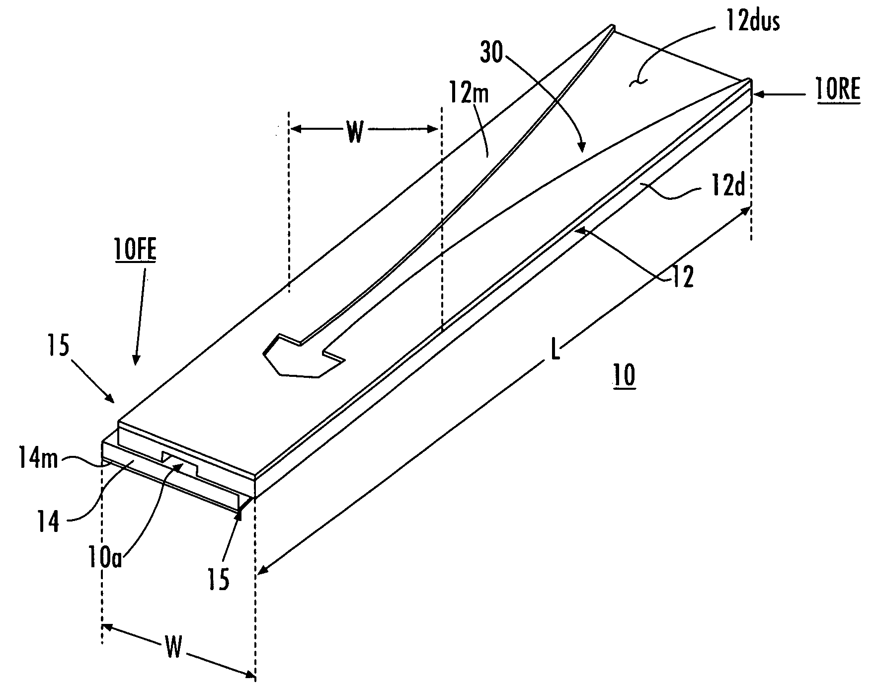
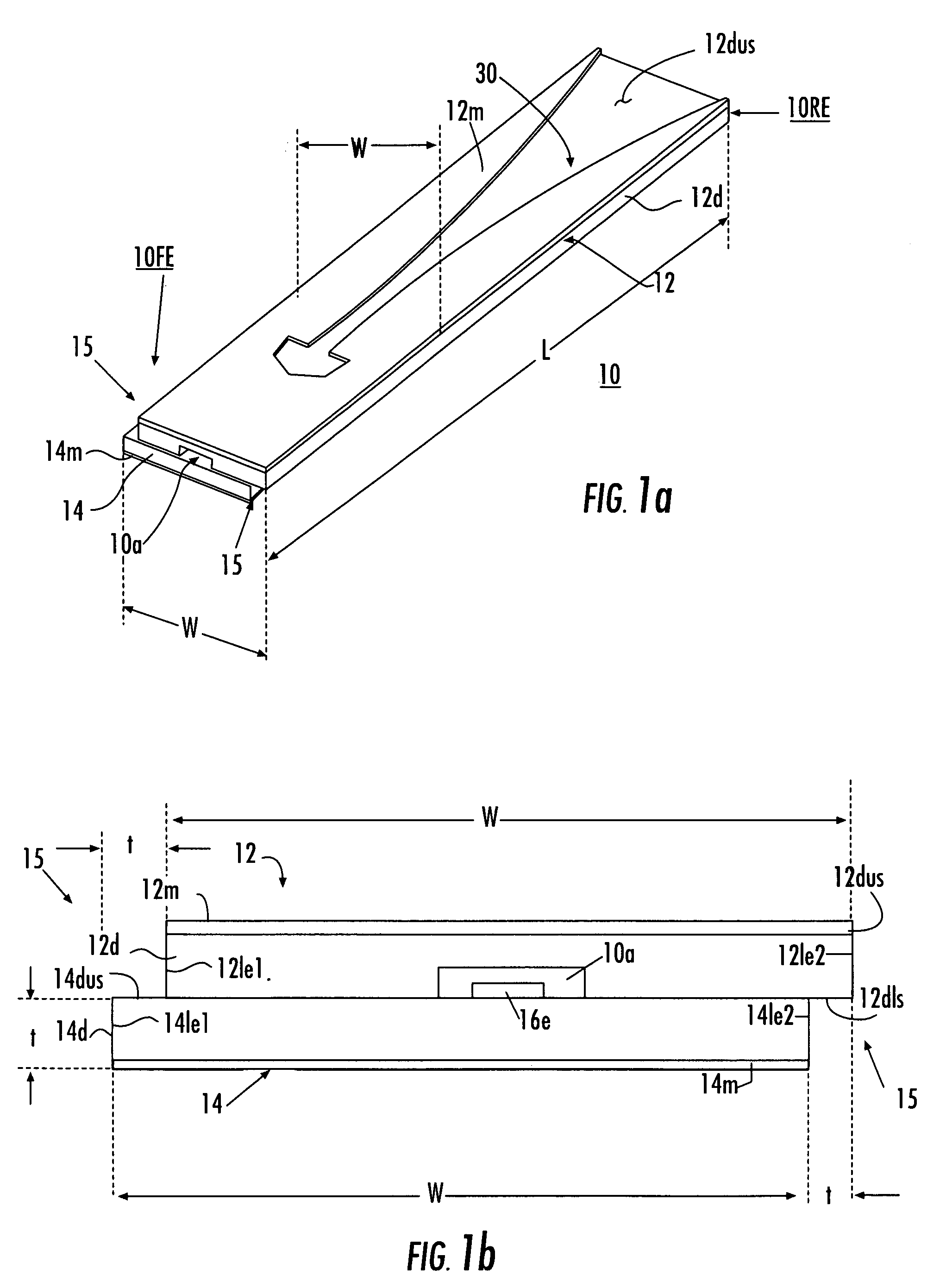
[0021]FIG. 1a is a simplified perspective or isometric view of a single horn antenna element 10 according to an aspect of the invention. Antenna 10 defines a feed end 10FE, a radiating end 10RE, and an overall length L. In FIG. 1a, the antenna element 10 is comprised of two juxtaposed “printed-circuit” or dielectric boards, namely an upper board 12 and a lower board 14, each having width W. Each of the upper board 12 and lower board 14 defines a feed end 12FE and 14FE, respectively, and a radiating end 12RE and 14RE, respectively. FIG. 1b illustrates a feed-end view of the arrangement of FIG. 1a. Upper board 12 includes two portions, namely a dielectric board portion ...


PUM


Abstract

A method for making a horn antenna array includes the steps of making first and second equal-size printed-circuit half-horn-elements, and offset-juxtaposing element pairs to make horn elements having a dielectric lip or step. A ground plane defining mutually intersecting crossed slot sets is loaded with horn elements with their lips interlocking near the slot crossings, to define the horn antenna array. The horn elements can be fed by pins extending through portions of the ground plane and into an aperture adjacent the feed elements of the horn elements. Electrical connections are made by fusion joining after the array is assembled.

Description

GOVERNMENTAL INTEREST[0001]This invention was made with government support under Contract / Grant SOMA 1TL391S01T00. The United States Government has a non-exclusive, non-transferable, paid-up license in this invention.FIELD OF THE INVENTION[0002]This invention relates to array antennas and to methods for making such antennas.BACKGROUND OF THE INVENTION[0003]Those skilled in the arts of antenna arrays and beamformers know that antennas are transducers which transduce electromagnetic energy between unguided- and guided-wave forms. More particularly the unguided form of electromagnetic energy is that propagating in “free space,” while guided electromagnetic energy follows a defined path established by a “transmission line” of some sort. Transmission lines include coaxial cables, rectangular and circular conductive waveguides, dielectric paths, and the like. Antennas are totally reciprocal devices, which have the same beam characteristics in both transmission and reception modes. For his...

Claims


Application Information

Patent Timeline
IPC IPC(8): H01Q13/10
CPCH01Q1/38H01Q21/064H01Q13/085
Inventor HARRIS, DANIEL W.HAHN, JOSEPH W.
Owner LOCKHEED MARTIN CORP
Why Eureka
Try Eureka