Imaging apparatus and imaging system

a technology of imaging apparatus and imaging system, which is applied in the field of image radiographing, can solve the problems of not being able to handle a radiographing method, unable to cope with various radiographing modes, and unable to handle high-speed moving image radiographing in some cases, so as to achieve the effect of easy handling

Inactive Publication Date: 2007-06-05
CANON KK
View PDF17 Cites 101 Cited by
  • Summary
  • Abstract
  • Description
  • Claims
  • Application Information

AI Technical Summary

Benefits of technology

[0013]Also, the area sensor made of amorphous silicon may be less negligibly affected by the after image. Especially when the moving image with a large contrast and quick motion of the subject is radiographed, the conventional correction method using the offset output after acquiring the radiographed output may be less negligibly affected by the after image.
[0016]It is an object of the present invention to provide an image radiographing apparatus and an image radiographing system, which can easily cope with a plurality of radiographing modes.
[0021]According to the present invention, the correction processing corresponding to the radiographing mode can be conducted. Accordingly, it is possible to easily cope with a plurality of radiographing modes. For example, any one of the still image radiographing mode, moving image radiographing mode, high speed moving image radiographing mode and energy subtraction radiographing mode is selected depending on the contents of correction processing.

Problems solved by technology

However, the conventional image radiographing apparatus and X-ray image radiographing system had the following problems.
That is, the conventional X-ray image radiographing system is only able to acquire the offset output for correction after acquiring the radiographed output and make the correction, as previously described, and may not cope with various radiographing modes.
Especially in radiographing a heart part of the little child requiring the high speed operation, the time for acquiring the offset output is rate determining, thereby impeding the high speed moving image radiographing in some cases.
Moreover, there is a problem that it is not possible to handle a radiographing method of acquiring a plurality of radiographed outputs of different energies successively as occurs with the energy subtraction radiographing.

Method used


Image

  • Imaging apparatus and imaging system
  • Imaging apparatus and imaging system
  • Imaging apparatus and imaging system

Examples


Embodiment Construction

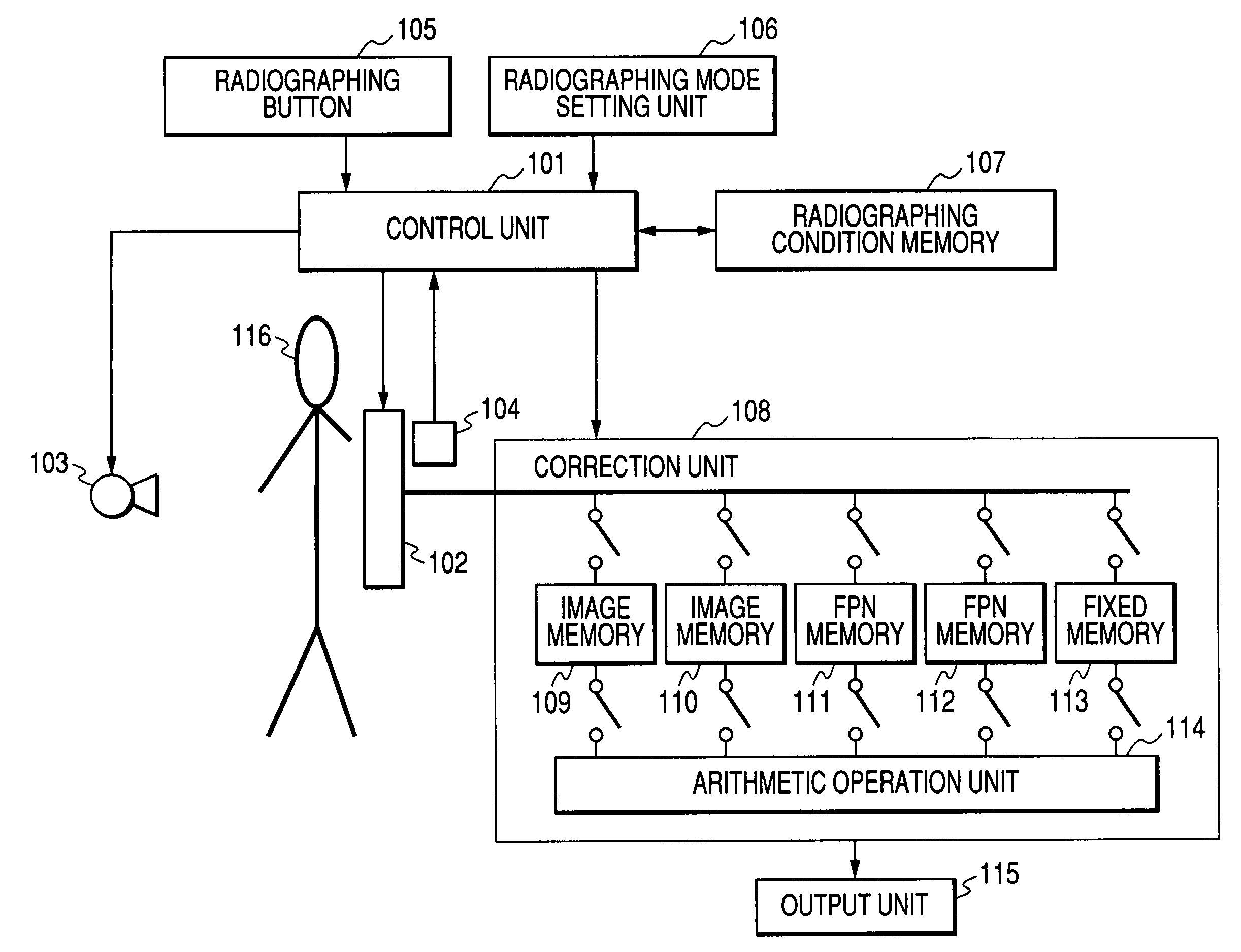
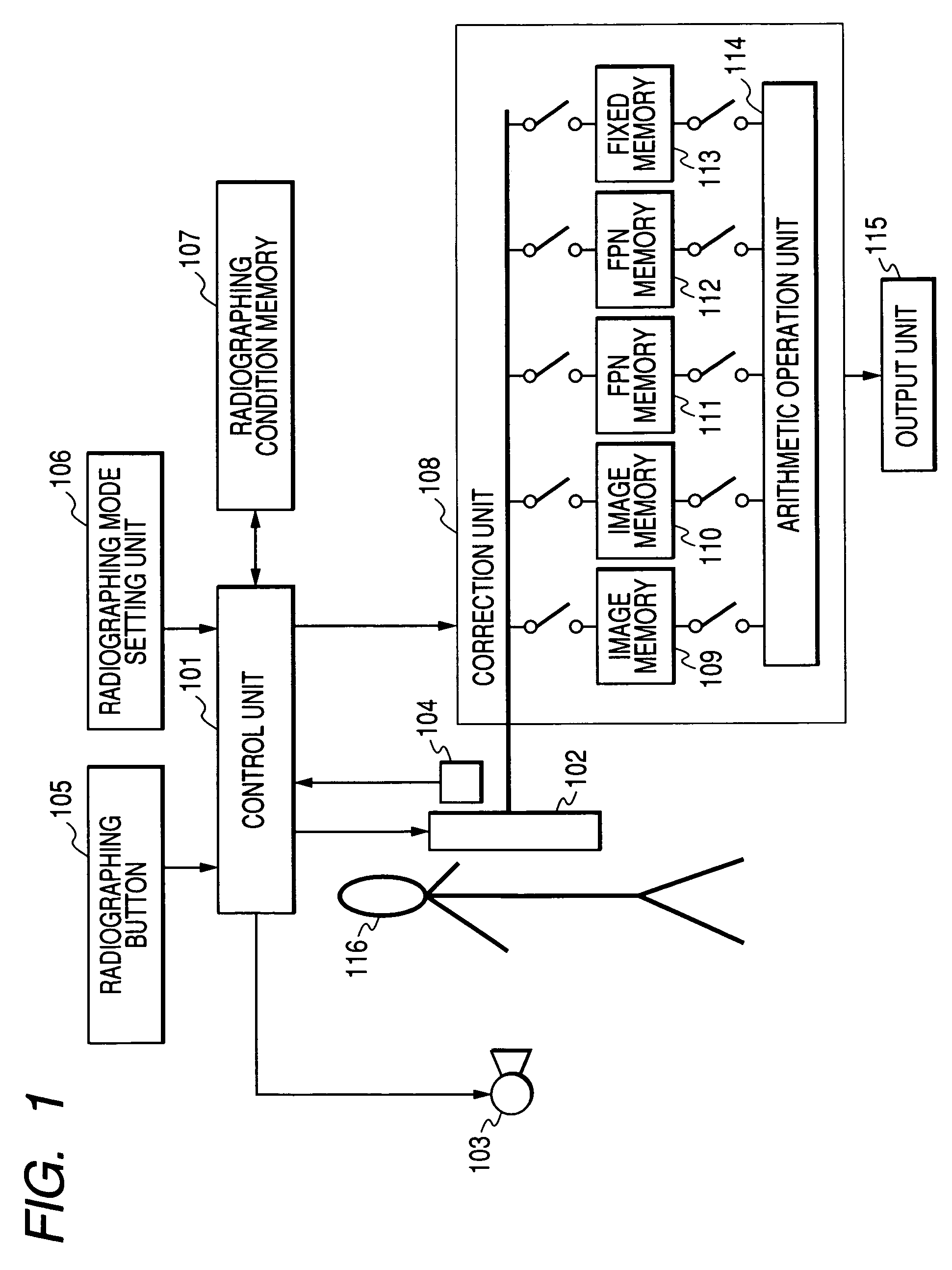
[0038]The preferred embodiments of the present invention will be described below with reference to the accompanying drawings. FIG. 1 is a typical diagram showing the configuration of an X-ray image radiographing system according to an embodiment of the present invention.

[0039]In this embodiment, an X-ray image radiographing system comprises an X-ray generator 103, a detection unit 102 for detecting an X-ray passed through a subject 116, a correction unit 108 for performing a correction processing for the data outputted from the detection unit 102, and an output unit 115 such as a monitor for outputting data processed by the correction unit 108, as shown in FIG. 1. Moreover, it comprises a control unit 101 for controlling the detection unit 102, the X-ray generator 103 and the correction unit 108, a radiographing condition memory 107 accessible by the control unit 101, a radiographing button 105 for making a radiographing request to the control unit 101, a radiographing mode setting ...


PUM

PropertyMeasurementUnit
speedaaaaaaaaaa
wavelength rangeaaaaaaaaaa
electricaaaaaaaaaa

Abstract

An X-ray image radiographing system comprises an X-ray generator, a detection unit, a correction unit for performing a correction processing for the data outputted from the detection unit, and an output unit for outputting data processed by the correction unit. Moreover, it comprises a control unit for controlling the detection unit, the X-ray generator and the correction unit, a radiographing condition memory accessible by the control unit, a radiographing button for making a radiographing request to the control unit, a radiographing mode setting unit 106 for setting a radiographing mode in the control unit, and a photo timer having an AE function. The radiographing mode setting unit may be constituted of a workstation. Thereby, it is possible to provide an image radiographing apparatus and system capable of easily coping with a plurality of radiographing modes.

Description

BACKGROUND OF THE INVENTION[0001]1. Field of the Invention[0002]The present invention relates to an image radiographing (hereinafter, radiographing including not only X-ray radiographing but also photographing for any wavelength range of radiation) apparatus and system, which acquires the corrected output by conducting arithmetic operation processing of a radiographed output and an offset output from an area sensor.[0003]2. Description of the Related Art[0004]Conventionally, an image photographing apparatus or radiographing apparatus employing a sensor array in which photoelectric conversion elements or TFTs formed of amorphous silicon or poly-silicon on a glass substrate are two-dimensionally arranged has been well known. In these apparatuses, it is common that electric charges photoelectrically transferred by photoelectric conversion elements are driven in matrix with TFTs and transferred to a reading device to read them.[0005]An offset correction and driving method for the image ...

Claims


Application Information

Patent Timeline
Patent Type & Authority Patents(United States)
IPC IPC(8): H05G1/64G03B42/02A61B6/00G01N23/04H04N5/232H04N5/32H04N5/335H04N5/361H04N5/378
CPCA61B6/405A61B6/482A61B6/585G01N23/04H04N5/32A61B6/00H04N5/3651H04N25/671
Inventor KAMESHIMA, TOSHIOENDO, TADAOYAGI, TOMOYUKITAKENAKA, KATSURO
Owner CANON KK
Why Eureka
Try Eureka