Pneumatic paintball gun and components

a paintball gun and pneumatic technology, applied in the field of paintball guns, to achieve the effect of convenient installation or removal and convenient removal

Active Publication Date: 2007-07-03
KORE OUTDOOR US INC +1
View PDF64 Cites 32 Cited by
  • Summary
  • Abstract
  • Description
  • Claims
  • Application Information

AI Technical Summary

Benefits of technology

[0004]According to one embodiment, a bolt assembly for a pneumatic paintball gun that incorporates principles of the present invention preferably comprises a bolt, a bolt linkage attached to the bolt, and a bolt removal assembly. The bolt linkage (or pin) preferably remains entirely inside the gun housing during operation of the gun. The bolt removal assembly preferably includes a bolt removal sleeve and an actuator (such as a handle or knob). Using the bolt removal assembly, the bolt assembly can preferably be removed as a single unit from the rear of the gun housing for maintenance and cleaning of the gun and its components. The actuator is preferably used to rotate the bolt sleeve and bolt for removal from the gun. A back plate is also preferably included to conceal the internal components of the marker and to prevent sand or other debris from entering the paintball gun through the back of the marker.
[0006]A pneumatic firing assembly, according to other principles of this invention, can also easily be installed or removed from a paintball gun. The pneumatic firing assembly preferably comprises a piston rod, a firing valve having a stem (or valve pin) positioned on or within an end of the piston rod, a piston chamber, and a firing mass positioned on an opposite end of the piston rod. The firing mass is preferably weighted to provide sufficient mass to activate the firing valve. A groove is preferably arranged in the firing mass for engaging a bolt linkage.
[0007]An electro-pneumatic paintball gun can be configured to utilize the above-described bolt assembly and pneumatic firing assembly. The paintball gun preferably includes a housing with a firing assembly chamber that receives the firing assembly and a bolt assembly chamber that receives the bolt assembly. A firing mass of the firing assembly is preferably arranged on a pneumatic piston. The firing mass preferably has a receiving groove for engaging a bolt linkage. A groove is preferably arranged in the housing between the firing assembly chamber and the bolt assembly to permit the bolt linkage to travel forwards and backwards with the pneumatic piston and firing mass. The electro-pneumatic paintball gun also preferably includes an opening in the rear of the housing that enables the firing assembly and bolt assembly to be readily removed from the paintball gun. A removable back plate can be provided to conceal the rear opening and prevent dirt or debris from entering the opening.

Problems solved by technology

While this approach provides a completely internal bolt assembly, it suffers because the breech block may become loose over time and may fail to align itself properly or have a sloppy feel during play.

Method used


Image

  • Pneumatic paintball gun and components
  • Pneumatic paintball gun and components
  • Pneumatic paintball gun and components

Examples


Embodiment Construction

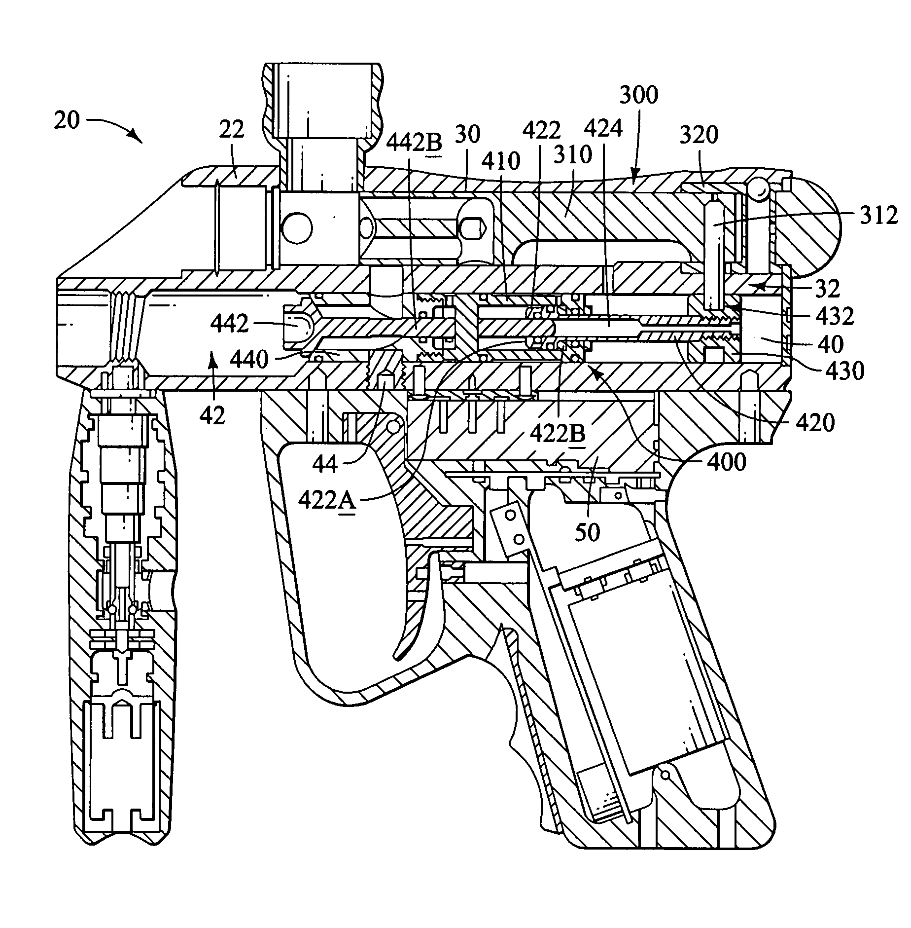
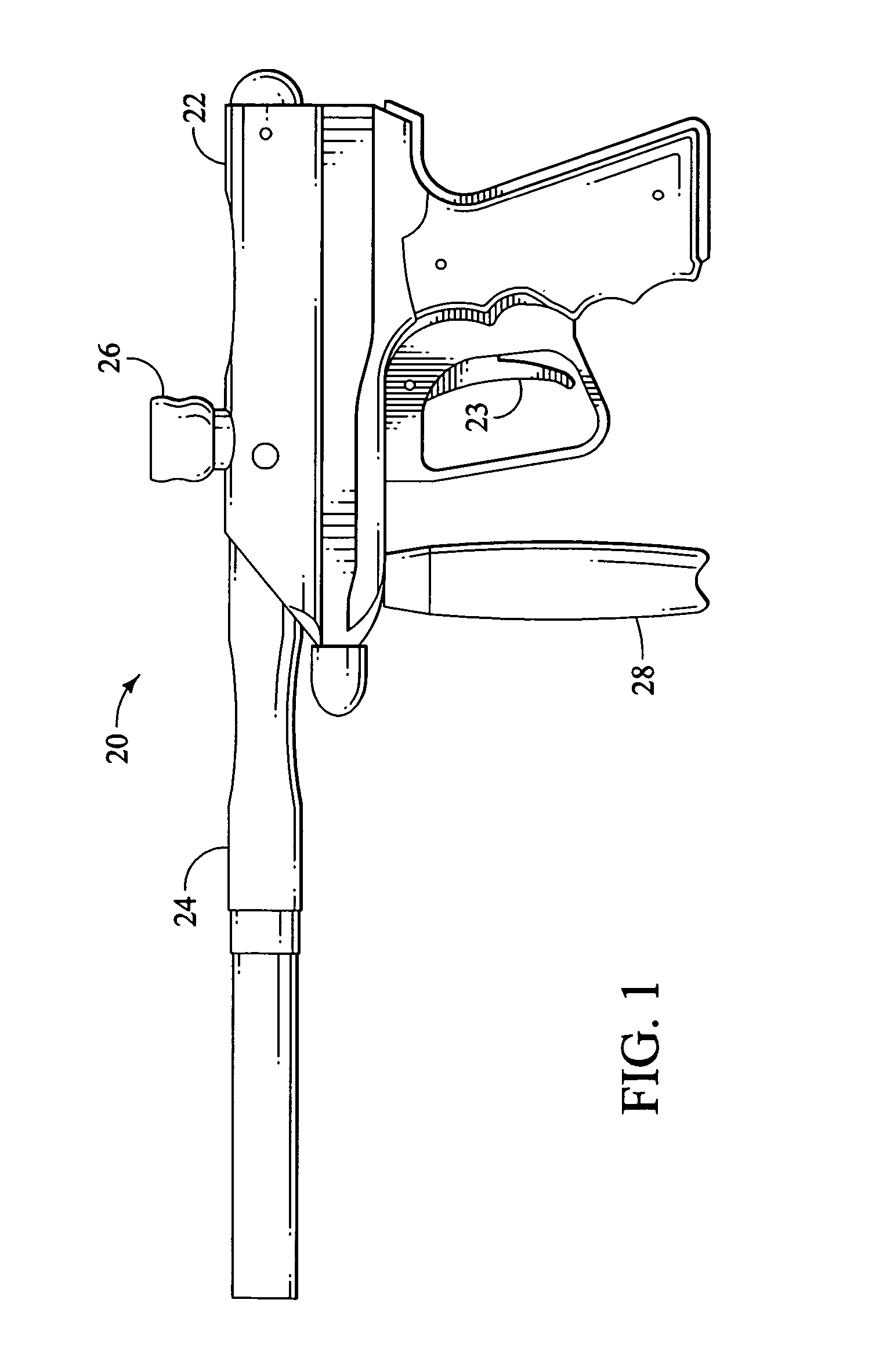
[0015]Various aspects and embodiments of the present invention will now be described in greater detail with reference to the accompany drawings. Beginning with FIG. 1, an electro-pneumatic paintball gun 20 according to one embodiment of the present invention includes a body 22. The gun 20 is preferably configured to receive pressurized gas from a pressurized gas source (such as a compressed gas tank) through a pressure regulator 28. As can be seen from FIG. 1, other than the trigger 23, there are no external moving parts in this embodiment of the invention. In addition, with the exception of the barrel 24 and feed tube 26, there are no open areas of the body 22 exposed to contamination and damage from dirt or other debris. In particular, a back plate 340 (see FIG. 2A) is preferably provided to removably cover a rearward opening in the paintball gun 20.

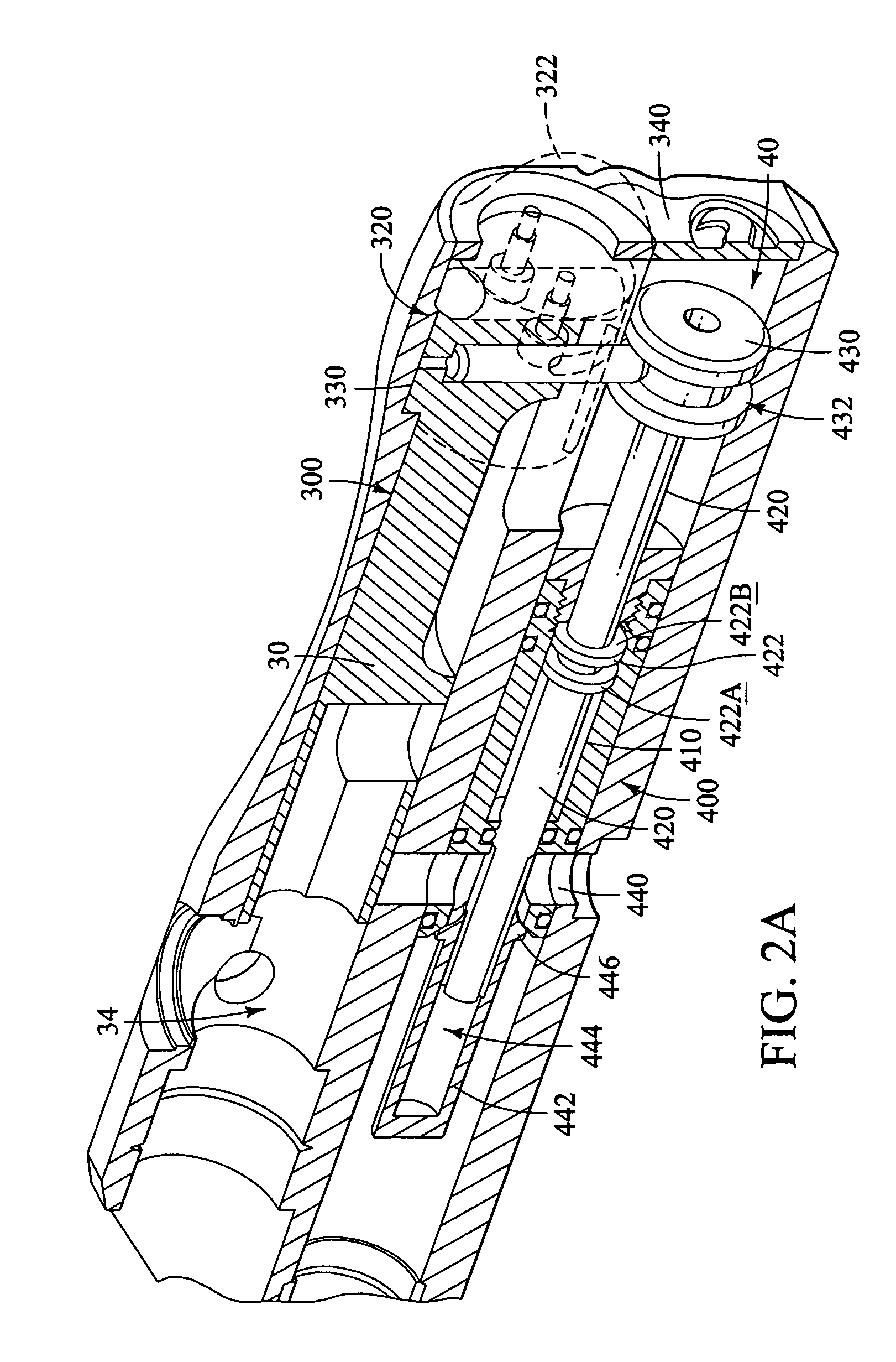
[0016]FIG. 2A is a vertically cross-sectioned perspective view of a first embodiment of the electro-pneumatic paintball gun 20 of FIG...


PUM


Abstract

An electro-pneumatic paintball gun preferably comprises a bolt assembly and a firing valve assembly that can be readily removed from the paintball gun. A bolt assembly preferably comprises a bolt sleeve. The bolt assembly is preferably removed by turning the bolt sleeve a predetermined rotational distance and then retracting the bolt assembly from a rearward opening in the paintball gun. The firing assembly preferably comprises a pneumatic piston rod and cylinder and a firing valve. A firing mass is preferably arranged on a rearward end of the piston rod. The forward end of the piston rod preferably engages the firing valve. The firing mass can include a groove for receiving a bolt linkage from the bolt assembly.

Description

BACKGROUND OF THE INVENTION[0001]This application relates generally to paintball guns (or “markers”). The inventive principles disclosed in this application primarily relate to electro-pneumatic paintball guns and components for electro-pneumatic paintball guns, including, among other things, bolt and firing assemblies.[0002]It is common for pneumatic paintball guns, including electro-pneumatic paintball guns, to use firing assemblies and bolt assemblies. For instance, in U.S. Pat. No. 6,349,711 (incorporated herein by reference) the firing assembly includes a firing valve actuated by a separate pneumatic ram assembly, and a bolt coupled to the pneumatic ram assembly through an externally-protruding removable bolt pin. To remove the bolt for maintenance or cleaning, the bolt pin is removed from the gun and the bolt is then allowed to slide out. This bolt pin is a separate part that must be kept track of during cleaning and maintenance.[0003]To avoid loss of the bolt pin, some paintb...

Claims


Application Information

Patent Timeline
Patent Type & Authority Patents(United States)
IPC IPC(8): F41B11/00F41B11/32
CPCF41B11/57F41B11/723F41B11/722F41B11/71
Inventor JONES, DANIAL S.
Owner KORE OUTDOOR US INC
Why Eureka
Try Eureka