Auto-focus lens module

a technology of auto-focus and lens module, which is applied in the direction of mountings, instruments, data recording, etc., can solve the problems of affecting the stability and accuracy of the movement of the lens holder, and the volume occupied by the lens module is quite large, so as to achieve a stable movement of the focusing axis, reduce the volume, and simplify the effect of components

Inactive Publication Date: 2007-08-28
E PIN INT TECH +1
View PDF4 Cites 61 Cited by
  • Summary
  • Abstract
  • Description
  • Claims
  • Application Information

AI Technical Summary

Benefits of technology

[0003]Therefore it is a primary object of the present invention to provide an auto-focus lens module that includes a lens holder, a coil and an upper frame clipped on outer circumference of the lens so as to form a lens holder set. And the coil is fixed between the lens holder and the upper frame. Two arched magnets are disposed on left and right sides of the coil and are positioned by a top cover while two springs are disposed on two guide pins on opposite angles of an inner surface of a base, pressing against the inner surface of the top cover. Thereby, electromagnetic force and spring compression force are used as driving force for adjusting focus. Furthermore, the components are simplified, the volume is minimized, and the lens holder moves stably for focusing.

Problems solved by technology

Thus the volume occupied by the lens module is quite large, against the principle of compact design.
However, the spring blades are easy to be deformed by external forces such as vibration, rebounding or after being used for a long time so that the stability and accuracy of the movement of the lens holder have been affected.

Method used


Image

  • Auto-focus lens module
  • Auto-focus lens module
  • Auto-focus lens module

Examples


Embodiment Construction

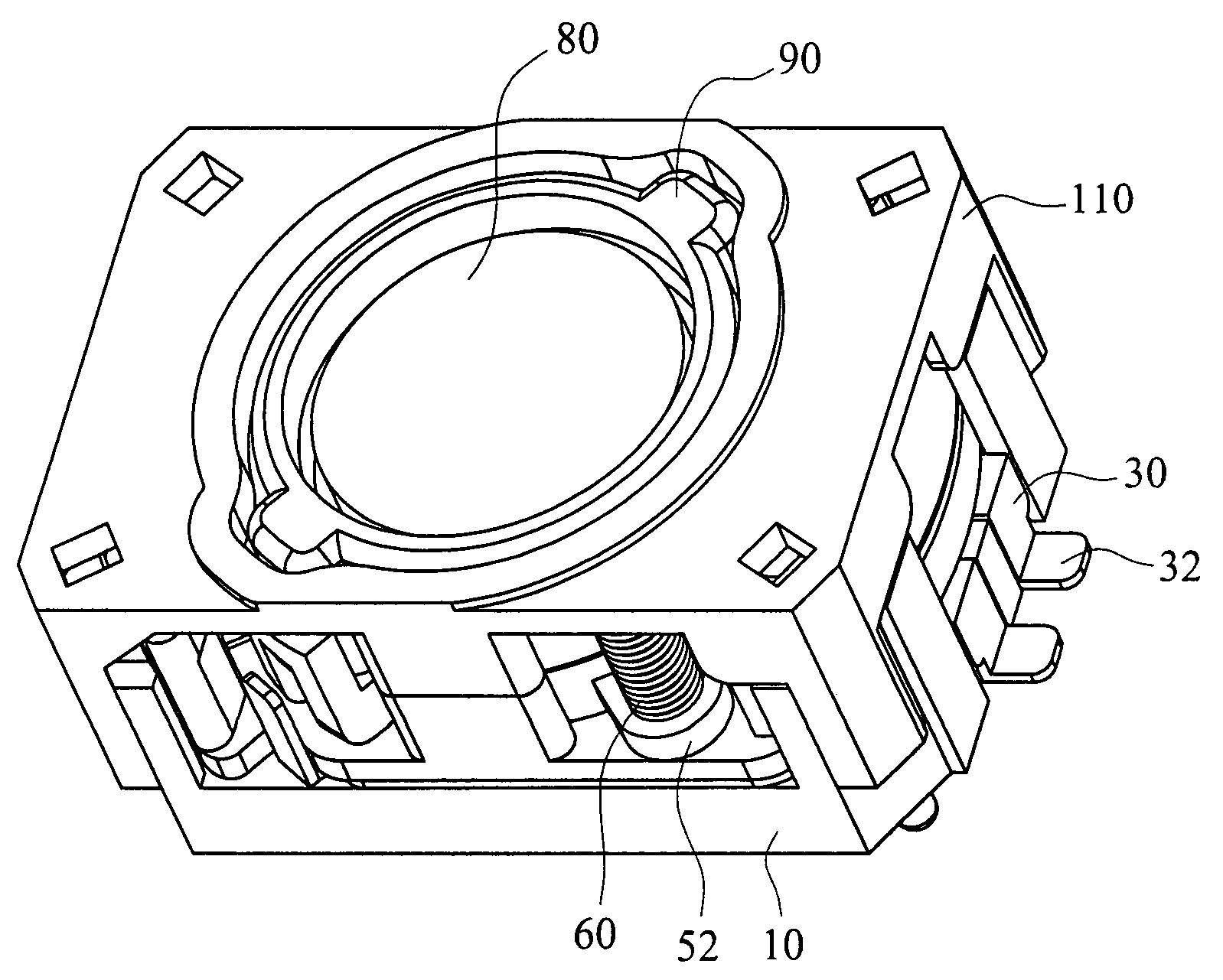
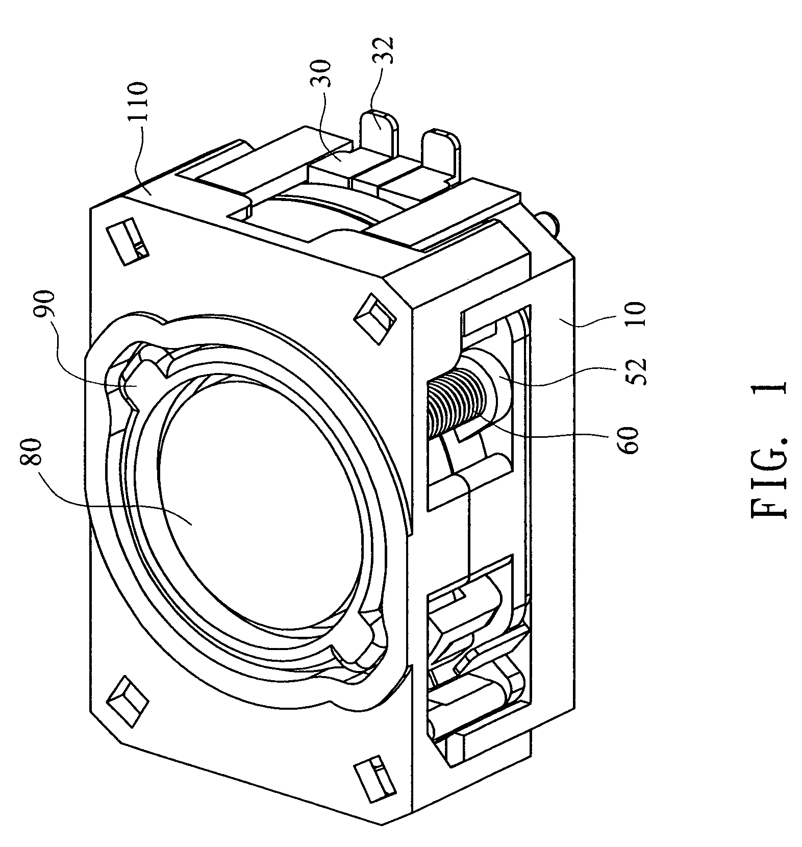
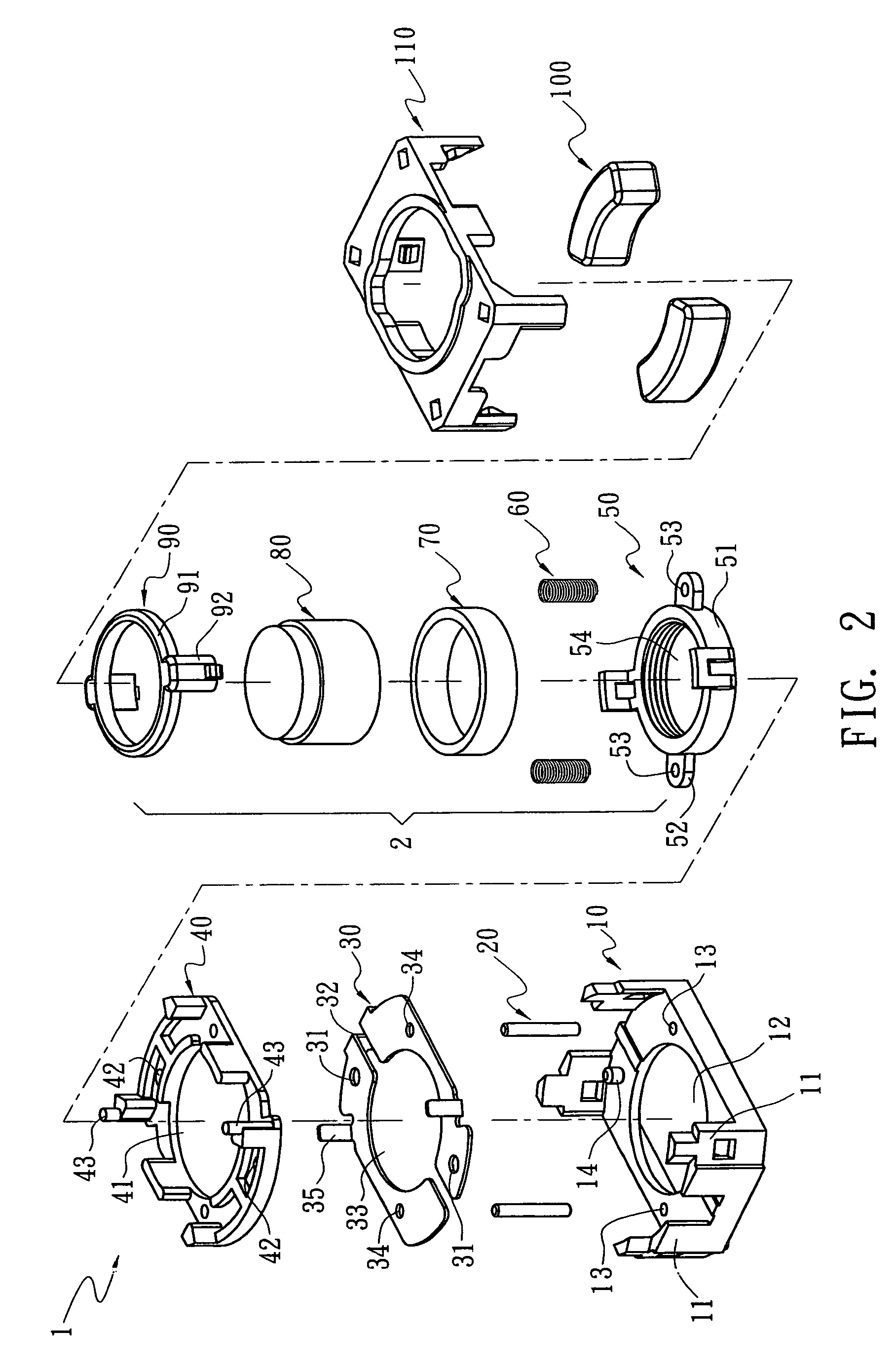
[0010]Refer from FIG. 1 to FIG. 4, a lens module 1 according to the present invention includes a base 10, two guide pins 20, two conductive plates 30, a bottom plate 40, a lens holder 50, two springs 60, a coil 70, a lens 80, a top plate 90, two magnets 100 and a top cover 110. Refer to FIG. 2, a lens holder set 2 composed by the lens holder 50, the coil 70 and the top plate 90 is clipped on circumference of the lens 80. The lens holder set 2, together with the two guide pins 20, two copper plates 30, the bottom plate 40 and the two magnets 100 are disposed between the base 10 and the top cover 110 so as to form the lens module 1. The lens holder set 2 moves forward or backward inside the lens module 1 for focus adjustment of the lens 80.

[0011]Refer to FIG. 5(A), the base is a rectangular frame with four stands 11 on four corners for fastening with the top cover 110. An insertion hole 12 on center of the base 10 is used to form an opening in optical pathway of lens 80. Two fixing ho...


PUM


Abstract

An auto-focus lens module uses electromagnetic force to drive a lens moving for focusing. The auto-focus lens is composed by a lens holder, a coil and an upper frame clipped on outer circumference of a lens so as to form a lens holder set. And the coil is fixed between the lens holder and the upper frame so as to reduce diameter and volume of the coil. Two arched magnets are disposed on left and right sides of the coil and are positioned by a top cover so that the volume of the magnets is reduced. Two springs are disposed on two guide pins on opposite angles, elastically supported between the lens holder and the inner surface of the top cover for providing the lens holder homogeneous support while moving for focusing. Thereby, the components of the lens module are simplified, the volume of the device is minimized, and the lens holder moves stably for focusing.

Description

BACKGROUND OF THE INVENTION[0001]The present invention relates to an auto-focus lens module, especially to a lens module that uses electromagnetic force as well as spring compression force as driving force.[0002]Either digital cameras or mobile phones with shooting function are disposed with a lens module that includes a focus adjusting device. The lens module available now has features of light weight, compact size, precision and durability. For example, it is guaranteed that the focus adjusting device should be operated at least two hundred thousand times without loosing. In conventional focus adjusting devices, electromagnetic force is used and the coils are surrounding a lens holder composed by a lens and a sleeve. A magnet arranged outside the coils is a circular magnet. Thus the volume occupied by the lens module is quite large, against the principle of compact design. Moreover, spring blades are used to balance the electromagnetic force. However, the spring blades are easy to...

Claims


Application Information

Patent Timeline
Patent Type & Authority Patents(United States)
IPC IPC(8): G02B7/02G02B15/14
CPCG02B7/026G02B7/08
Inventor SHYU, SAN-WOEIHUANG, SHIH-CHAOCHU, HSIEN-RU
Owner E PIN INT TECH
Why Eureka
Try Eureka