Systems and methods for enabling a mobile user to notify an automated monitoring system of an emergency situation
Inactive Publication Date: 2007-08-28
SIPCO
View PDF560 Cites 281 Cited by
Summary
Abstract
Description
Claims
Application Information
AI Technical Summary
This helps you quickly interpret patents by identifying the three key elements:
Problems solved by technology
Method used
Benefits of technology
Problems solved by technology
A problem with expanding the use of automated monitoring systems is the cost of the sensor/actuator infrastructure required to monitor and control such systems.
Another prohibitive cost of control systems is the installation and operational expenses associated with the site controller.
Another problem with using automated monitoring system technology is the geographic size of automated monitoring systems.
In a hard-wired automated monitoring system, the geographic s
Method used
Image
Click on the blue label to locate the original text in one second.
Reading with bidirectional positioning of images and text.
Examples
Embodiment Construction
[0022]Having summarized the invention above, reference is now made in detail to the description of the invention as illustrated in he drawings. While the invention will be described in connection with these drawings, there is no intent to limit it to the embodiment or embodiments disclosed therein. On the contrary, the intent is to cover all alternatives, modifications and equivalents included within the spirit and scope of the invention as defined by the appended claims.
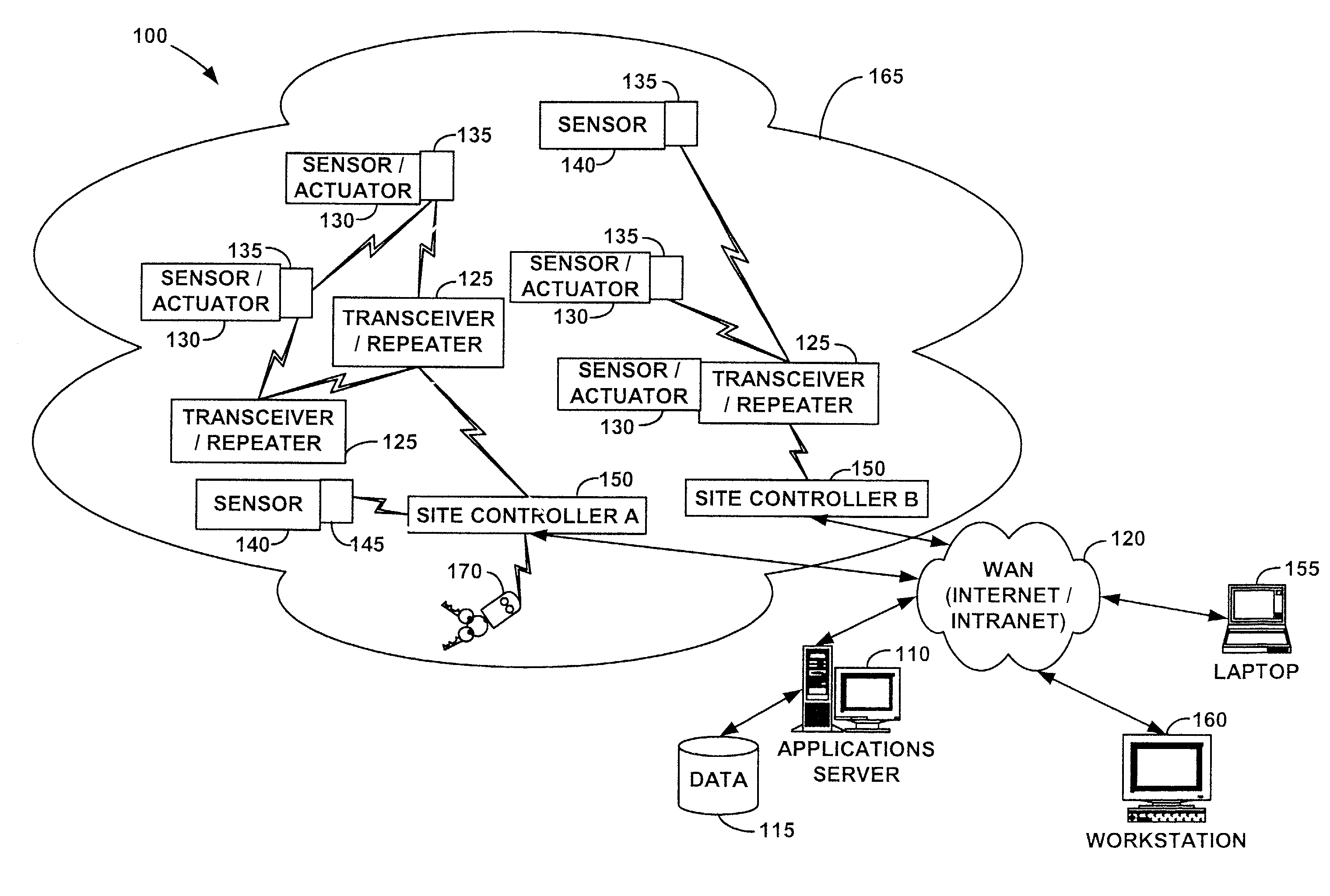
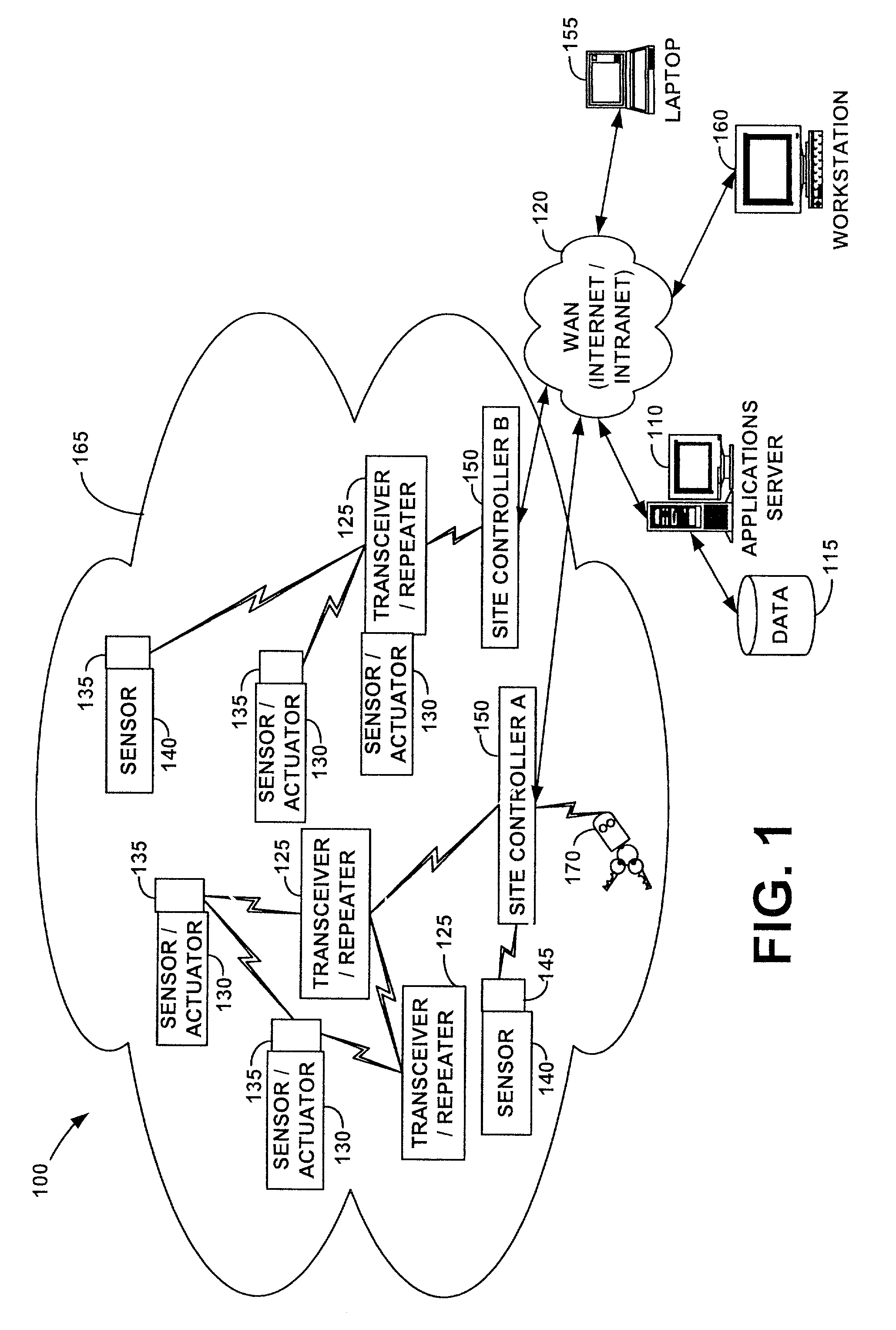
[0023]Reference is now made to FIG. 1, which is a schematic diagram illustrating an automated monitoring system 100 according to the present invention. The automated monitoring system 100 may comprise one or more applications servers 110 (one being shown for simplicity of illustration), one or more database servers 115, a WAN 120, one or more repeaters 125, one or more sensor / actuators 130, one or more transceivers 135, one or more sensors 140, one or more transmitters 145, and at least one site controller 150. As f...
PUM
Abstract
Systems and methods for enabling a mobile user to notify an automated monitoring system of an emergency situation are provided. The automated monitoring system may be configured for monitoring and controlling a plurality of remote devices and may comprise a site controller in communication with the plurality of remote devices via a plurality of transceivers defining a wireless communication network and in communication with a host computer via a wide area network. Briefly described, one such method comprises the steps of: receiving notification that the mobile user desires to initiate transmission of an emergency message to the site controller; determining the identity of the mobile user; and providing an emergency message over the wireless communication network for delivery to the site controller, the emergency message indicating the identity of the mobile user.
Description
CROSS-REFERENCE TO RELATED APPLICATIONS[0001]This application is a continuation-in-part of U.S. patent application Ser. No. 09 / 704,150, filed Nov. 1, 2000, now U.S. Pat. No. 6,891,838, and entitled “System and Method for Monitoring and Controlling Residential Devices;” U.S. patent application Ser. No. 09 / 271,517, filed Mar. 18, 1999, now abandoned, and entitled “System For Monitoring Conditions in a Residential Living Community;” and U.S. patent application Ser. No. 09 / 439,059, filed Nov. 12, 1999, now U.S. Pat. No. 6,437,692 and entitled “System and Method for Monitoring and Controlling Remote Devices.” Each of the identified U.S. patent applications is hereby incorporated by reference in its entirety. This application also claims the benefit of U.S. Provisional Application Ser. No. 60 / 224,047, filed Aug. 9, 2000, and entitled “Design Specifications for a Personal Security Device (FOB),” which is hereby incorporated by reference in its entirety.FIELD OF THE INVENTION[0002]The prese...
Claims
Application Information
Patent Timeline
Application Date:The date an application was filed.
Publication Date:The date a patent or application was officially published.
First Publication Date:The earliest publication date of a patent with the same application number.
Issue Date:Publication date of the patent grant document.
PCT Entry Date:The Entry date of PCT National Phase.
Estimated Expiry Date:The statutory expiry date of a patent right according to the Patent Law, and it is the longest term of protection that the patent right can achieve without the termination of the patent right due to other reasons(Term extension factor has been taken into account ).
Invalid Date:Actual expiry date is based on effective date or publication date of legal transaction data of invalid patent.